


Product Description
34 MS-9200UDLS PN 52750:E1 01/27/09
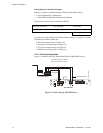
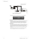
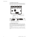
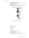
1.8.7.5.3 ANN-I/O Connection to FACP
The ANN-I/O connects to the FACP via the ANN-BUS as illustrated in Figure 1.8.
After the ANN-I/O is connected to the panel, it must be added to the system via
FACP programming. Refer to the section titled "ANN-I/O Options" on page 120.
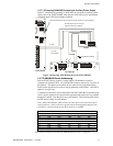
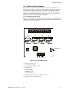
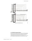
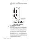
1.8.7.5.4 ANN-I/O Module LED Wiring
There are four 12-pin connectors on the ANN-I/O module for connecting LEDs.
Each set of 10 LEDs get their power from Pin 11 of the corresponding connector.
Internal resistors are sized so that there is approximately 10 mA of current for each
LED. No series resistors are required. LED outputs can be mapped to output
circuits. Refer to the programming section titled "ANN-I/O Options" on page 120
of this manual.
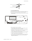
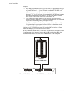
The LEDs are wired as illustrated in Figure 1.9. Note that the illustration depicts
only connectors P1 and P2. Wiring is identical for P3 (LEDs 21-30) and P4 (LEDs
31-40).
Figure 1.8 ANN-I/O Connection to FACP
ANN-I/O Module
MS-9200UDLS
ANN-BUS and power wiring are
supervised and power-limited
92udlstoannio.cdr
ANN-BUS/ACS BUS
24 VDC
nonresettable