


Programming
118 MS-9200UDLS PN 52750:E1 01/27/09
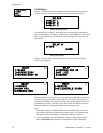
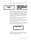
3.6.9.1.3 ANN-BUS Options
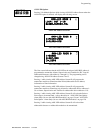
Pressing 3 for ANN-BUS Options, while viewing the Annunciators screen, will
cause the following screens to be displayed:.
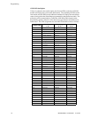
A printer module, graphic annunciator module, LCD annunciator module, LED
annunciator module and relay module can be programmed into the MS-9200UDLS
system. These devices communicate with the FACP over the ANN-BUS terminals
on the control panel.
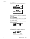
3.6.9.1.3.1 ANN-BUS Enabled
The ANN-BUS must be enabled if any modules are connected to the ANN-BUS
terminals. To enable the ANN-BUS, press 1 while viewing ANN-BUS screen #1 so
that the display reads ANN-BUS Enabled Yes. Each press of the 1 key will cause the
display to toggle between ANN-BUS Enabled Yes and ANN-BUS Enabled No.
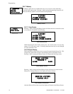
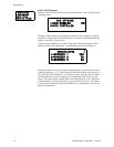
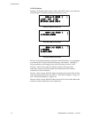
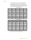
3.6.9.1.3.2 Modules Installed
If an ANN-BUS module is installed, press 2 for Modules Installed while viewing
ANN-BUS screen #1 to select ANN-BUS addresses for the module(s). The
following screen will be displayed.
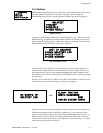
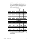
Pressing the down arrow key will allow the programmer to view additional screens
displaying Addresses 1-8. To select one or more addresses for the installed
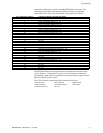
module(s), press the number key corresponding to the module address in each
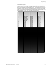
screen. The following screen will be displayed for each address:
ANN-BUS
1=ENABLED NO
2=MODULES INSTALLED
3=AUTO-CONFIGURE
ANN-BUS Screen #1
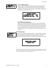
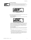
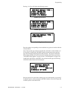
ANN-BUS
1=ANN-S/PG OPTIONS
2=ANN-80 OPTIONS
ANN-BUS Screen #2
ANN-BUS MODULES
1=ADDR. 1 NONE
2=ADDR. 2 NONE
3=ADDR. 3 NONE
ANN-BUS Modules Screen #1
ANN-BUS MODULES
ANN-BUS ADDRESS #
1=TYPE NONE
ANN-BUS Address Screen