


Software Zones
MS-9200UDLS PN 52750:E1 01/27/09 191
APPENDIX A Software Zones
A.1 Correlations
Setup and configuration of an addressable system is different than a conventional system. In a
conventional system, assignment of input devices (smoke detectors, pull stations, heat detectors,
etc.) to zones is accomplished through wiring. The wiring is direct from clearly marked panel
terminals to any device assigned to a particular zone. Connection of output devices (horns, bells,
strobes, etc.) in a conventional system is accomplished by direct wiring of the output devices to
Notification Appliance Circuit terminals.
In an addressable system, a minimum of a single pair of wires (SLC communication loop) is used
to connect all addressable input and output devices. Communications between the FACP (Fire
Alarm Control Panel) and all addressable devices takes place over the wire pair which originates
from the FACP. Software programming is used to configure the system as opposed to direct wiring.
Zone assignments are created via software means, hence the term software zones.
Setup of an MS-9200UDLS software zone is accomplished by panel programming. Each
addressable device can be assigned to a maximum of five software zones. Each software zone,
however, may have from 1 to 99 addressable input devices assigned to it and from 1 to 99
addressable output devices assigned to it.
Monitor and control modules comprise one group of 99 addresses, with each module having a
unique address from 1 to 99. Detectors comprise a separate group of 99 addresses, each detector
having a unique address from 1 to 99 in its group. Be careful not to duplicate addresses within any
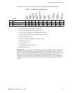
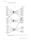
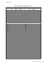
one group (modules and detectors). Refer to the following page for an example of zoning.
In the example on the following page:
• Zone 01 has the following addressable devices assigned to it:
SD350 smoke detectors with addresses 01 and 02
MMF-300 monitor module with address 01
MMF-302 monitor module with address 02 and 03
CMF-300 control modules with addresses 05, 06, 07, 09 and 13
• Zone 02 has the following addressable devices assigned to it:
MMF-302 monitor module with addresses 02 and 03
CP350 smoke detectors with addresses 03 and 04
CMF-300 control modules with addresses 08, 09 and 10
• Zone 03 has the following addressable devices assigned to it:
SD350 smoke detectors with addresses 05, 06 and 07
MMF-302 control module with address 04
CMF-300 control modules with addresses 09, 11 and 12
The example points out some of the key assignment features of the MS-9200UDLS. Addresses of
detectors are not duplicated. Addresses of monitor and control modules are not duplicated. The
control module with address 09 is assigned to three software zones (providing floor above and floor
below). Be careful to properly plan the installation prior to installing any devices.