


Product Description
20 MS-9200UDLS PN 52750:E1 01/27/09
1.6 Components
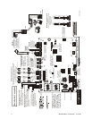
Main Circuit Board
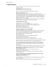
The main circuit board contains the system’s CPU, power supply, other primary
components and wiring interface connectors. The 4XTMF option module plugs in and
is mounted to the main circuit board.
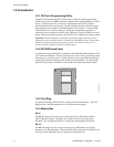
Cabinet
The MS-9200UDLS backbox provides space for two batteries (up to 18 Amp Hour).
Ample knockouts are provided for system wiring. Also available is an optional dress
panel (DP-9692), which mounts to the inside of the cabinet (required by ULC for
Canadian installations).
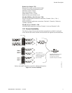
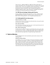
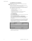
Transformer Assembly
One 100VA transformer is provided standard
with the panel (3.6 amps maximum). An
optional 100 VA transformer XRM-24B
(XRM-24BE for the MS-9200UDLSE) is
available to provide maximum system and
accessory power (6.6 amp total). Note that the
XRM-24B and XRM-24BE are only suitable for
use with MS-9200UDLS(E) with main circuit
board number 03611. This circuit board can also be identified by using the software
revision of #9200UDV4.0 (meaning version 4.0) or later.
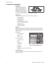
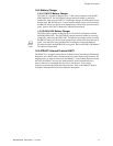
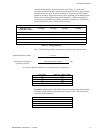
Batteries
The MS-9200UDLS cabinet provides space
for two batteries (up to 18 Amp Hour).
Batteries larger than 18 Amp Hour require an
external charger such as the CHG-75 or
CHG-120F and a UL listed battery box such
as the BB-55F. Batteries must be ordered separately.
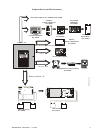
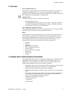
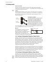
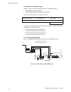
1.6.1 Intelligent Addressable Detectors: Newer Series
Intelligent, addressable detectors provide information to the control panel on an SLC
Signaling Line Circuit (refer to the SLC Wiring Manual for detailed information on
device installation, wiring and operation). This allows the control panel to continually
process the information to determine the status (alarm, trouble, maintenance or normal)
of each detector. Each detector responds to an SLC address that is set in the detector
head using built-in rotary decimal switches. The maximum address cannot exceed
address 99. Note that a blinking LED on an intelligent detector indicates
communication between the detector and the control panel.
These devices (350 Series or newer) can operate in CLIP mode (Classic Loop Interface
Protocol) or LiteSpeed mode to provide a quicker response. They are also compatible
with older 300 Series devices. If a mix of old and new series devices are installed on
the same loop, the FACP must be programmed to operate in CLIP mode. Refer to the
SLC Wiring Manual for a list of compatible addressable detectors.
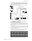
1.6.2 Intelligent Addressable Modules: Newer Series
The newer series of Control Modules and Monitor Modules provide an interface
between the control panel and conventional notification and initiating devices. Each
module can be set to respond to an address with built-in rotary switches. The maximum
address cannot exceed address 99. Note that a blinking LED on an addressable module
indicates communication between the module and the control panel.
See Page
Standard
XRM-24B(E)
Optional
XRM-24B(E)
9200xfor.cdr
-
-
+
+
Battery Cable P/N 75287
9200batt.cdr
Reference
Manual