


Product Description
16 MS-9200UDLS PN 52750:E1 01/27/09
1.2 Specifications
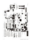
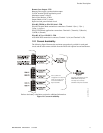
Refer to Illustration on page 10 for terminal locations and connections.
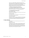
AC Power - TB11
MS-9200UDLS: 120 VAC, 60 Hz, 3.0 amps
MS-9200UDLSE: 240 VAC, 50 Hz, 1.5 amps
Wire size: minimum 14 AWG (2.00 mm
2
) with 600 V insulation
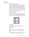
Battery (Lead Acid Only) - J9
Maximum Charging Circuit: Normal Flat Charge - 27.6 VDC @ 0.80 amp
Maximum Battery Charger Capacity: 18 Amp Hour (FACP cabinet holds maximum of
two 18 Amp Hour batteries. For greater than 26 Amp Hour up to 120 Amp Hour
batteries, use the CHG-75 or CHG-120F Battery Charger and BB-55F Battery Box).
Minimum Battery Size: 7 Amp Hour
Note: Jumper JP5, on the FACP main circuit board, must be removed to disable the
FACP battery charger when using an external battery charger.
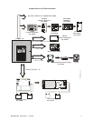
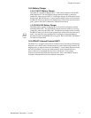
Communication Loop - TB10
24 VDC nominal, 27.6 VDC maximum
Maximum length - refer to "Wire Requirements" on page 205)
Maximum loop current is 400 mA (short circuit) or 100 mA (normal)
Maximum loop resistance is 40 ohms
Supervised and power-limited circuit
Refer to SLC Loop manual for wiring information
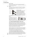
Notification Appliance Circuits - TB3 & TB4
Each Terminal Block provides connections for two Style Y (Class B) or one Style Z
(Class A) for a total of Four Style Y (Class B) or two Style Z (Class A) NACs
Style is configured using NACKEY card plugged into JP6 on main board
Special Application full-wave rectified power
Power-limited circuitry
NAC wiring requirements refer to "NAC Wiring" on page 207
Nominal operating voltage: 24 VDC
Current-limit: fuseless, electronic, power-limited circuitry
Maximum signaling current per circuit: 2.5 amps (see Figure 1.1 on page 17)
End-of-Line Resistor: 4.7 kΩ, ½ watt (P/N 71252 UL listed) for Style Y (Class B) NAC
Refer to the Device Compatibility Document for listed compatible devices
Two Programmable Relays and One Fixed Trouble Relay - TB5, TB6 & TB7
Contact rating: 2.0 amps @ 30 VDC (resistive), 0.5 amps @ 30 VAC (resistive)
Form-C relays
Refer to Figure 2.6 on page 50 for information on power-limited relay circuit wiring
Nonresettable or Resettable Special Application Power (24 VDC Nominal) -
TB1, Terminals 1 (+) & 2 (-)
Jumper selectable (JP4) for conversion to resettable power output
Maximum ripple voltage: 10mV
RMS
Total DC current available from each output is up to 0.300 amps (see Figure 1.1)
Power-limited circuit
Four-Wire Resettable Special Application Smoke Detector Power (24 VDC
nominal) - TB1, Terminals 3 (+) & 4 (-)
Maximum ripple voltage: 10 mV
RMS
Up to 0.300 amps is available for powering 4-wire smoke detectors (see Figure 1.1)
Power-limited circuit
Refer to the Device Compatibility Document for listed compatible devices