


Wire Requirements
206 MS-9200UDLS PN 52750:E1 01/27/09
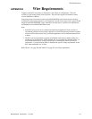
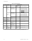
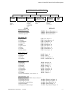
Table E.1 FACP Wire Specifications
CIRCUIT CONNECTIONS WIRE REQUIREMENTS
Circuit Type Circuit Function Wire Type and Limitations
Recommended
Max. Distance
Feet (meters)
Wire Gauge and Compatible Brands
SLC loop
(power-limited)
Connects to
Addressable
Devices
CLIP MODE
Twisted, shielded pair
40 ohms maximum per
length of Style 6 and 7
loops. 40 ohms per branch
maximum for Style 4 loops
10,000 (3,000 m)
8,000 (2,400 m)
4,875 (1,450 m)
3,225 (980 m)
12 AWG (3.25 mm
2
): Genesis 4410,
Signal 98230, Belden 9583, WPW999
14 AWG (2.00 mm
2
):Genesis 4408 & 4608
Signal 98430, Belden 9581, WPW995
16 AWG (1.30 mm
2
): Genesis 4406 & 4606
Signal 98630, Belden 9575, WPW991
Direct Burial Cable
Isotec NP713110VNQ-S
18 AWG (0.75 mm
2
): Genesis 4402 & 4602
Signal 98300, Belden 9574, WPW975
Direct Burial Cable Isotec NP714110VNQ-S
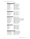
LITESPEED
MODE
Twisted, unshielded pair
40 ohms maximum per
length of Style 6 and 7
loops. 40 ohms per branch
maximum for Style 4 loops
10,000 (3,000 m)
8,000 (2,400 m)
4,875 (1,450 m)
3,225 (980 m)
12 AWG (3.25 mm
2
): Belden 5020UL &
6020UL, Genesis WG-4315 & WG-4515
14 AWG (2.00 mm
2
):Belden 5120UL &
6120UL, Genesis WG-4313 & WG-4513
16 AWG (1.30 mm
2
): Belden 5220UL &
6220UL, Genesis WG-4311 & WG-4511
18 AWG (0.75 mm
2
): Belden 5320UL &
6320UL, Genesis WG-4306 & WG-4506
Untwisted, unshielded pair
1
3,000 (900 m)
12-18 AWG (3.25 - 0.75 mm
2
) using listed wire
ACS-BUS
(EIA-485)
(power-limited)
Connects to
annunciator
modules
Twisted pair with a
characteristic impedance of
120 ohms
6,000 (1,800 m)
12 AWG (0.75 mm
2
)
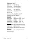
ANN-BUS
(EIA-485)
(power-limited)
Connects to
annunciator
modules
Twisted pair 6,000 (1,800 m) Refer to "ANN-BUS Wiring" on page 24 for
information on device wiring
EIA-232
(power-limited)
connects to remote
PC computer
Twisted, shielded pair 50 (15 m)
18 AWG (0.75 mm
2
) minimum
MMF-300 and
MMF-301
(power-limited)
Initiating Device
Circuit
Maximum loop wire
resistance is 40 ohms for the
MMF-300 and 20 ohms for
the MMF-301
2,500 (760 m)
12-18 AWG (3.25 - 0.75 mm
2
)
MMF-302
(power-limited)
Initiating Device
Circuit
No more than a 2.4 volt drop
allowed at end of circuit.
Maximum loop wire
resistance is 25 ohms
2,500 (760 m)
12-18 AWG (3.25 - 0.75 mm
2
)
CMF-300
(power-limited)
Notification
Appliance
Circuit
In alarm, no more than a 1.2
volt drop allowed at end of
circuit
Distance limitation
set by 1.2 volt
maximum line drop
12-18 AWG (3.25 - 0.75 mm
2
)
Remote Sync
Output
Provides strobe
and normal sync
for remote NAC
power supplies
Untwisted, unshielded pair
wire
Distance set by 295
ohm resistance
limitation
12-18 AWG (3.25 - 0.75 mm
2
)
Table Footnote
1. When using untwisted, unshielded wire, full conduit is recommended for optimum EMI/RFI protection.