


Product Description
24 MS-9200UDLS PN 52750:E1 01/27/09
1.8.7 ANN-BUS Annunciators/Modules
WARNING! Disconnect all sources of power (AC and DC) before installing or
removing any modules or wiring.
The legacy ACS annunciators may not be used if new ANN-BUS annunciators are
being used due to incompatible serial communication protocols.
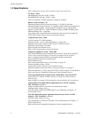
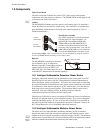
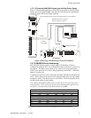
A variety of optional devices can be connected to the FACP ANN-BUS communication
circuit. ANN Series devices can be connected to the ACS (EIA-485) terminals on
TB-9. Compatible devices include the following:
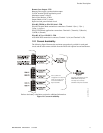
• ANN-80 LCD Annunciator
• ANN-S/PG Serial/Parallel Printer Interface Module
• ANN-I/O LED Driver Module
• ANN-LED Annunciator Module (alarm, trouble, supervisory LEDs)
• ANN-RLED Annunciator Module (red alarm LEDs only)
• ANN-RLY Relay Module
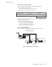
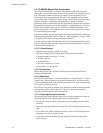
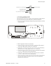
1.8.7.1 ANN-BUS Wiring
This section contains information on calculating ANN-BUS wire distances and the
types of wiring configurations (Class B).
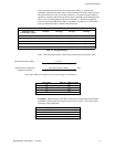
1.8.7.1.1 Calculating Wiring Distance for ANN-BUS Modules
The following instructions will guide the installer in determining the type of wire
and the maximum wiring distance that can be used with FACP ANN-BUS
accessory modules.
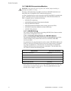
To calculate the wire gauge that must be used to connect ANN-BUS modules to the
FACP, it is necessary to calculate the total worst case current draw for all modules
on a single 4-conductor bus. The total worst case current draw is calculated by
adding the individual worst case currents for each module. The individual worst
case values are shown in the following table:
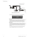
Note: Total worst case current draw on a single ANN-BUS cannot exceed 0.5 amp.
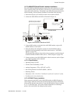
If current draw exceeds 0.5 amps, refer to "Powering ANN-BUS Devices from
Auxiliary Power Supply" on page 27.
Model Number Worst Case Current Draw
ANN-80 LCD Annunciator 0.040 amps
ANN-S/PG Serial/Parallel Printer Interface Module 0.040 amps
ANN-I/O LED Driver Module 0.200 amps
ANN-(R)LED Annunciator Module 0.068 amps
ANN-RLY Relay Module 0.075 amps