


Installation
50 MS-9200UDLS PN 52750:E1 01/27/09
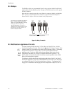
2.4 Relays
The FACP provides two programmable Form-C relays and one fixed fail-safe Form-C
trouble relay, all with contacts rated for 2.0 amps @ 30 VDC (resistive) or 0.5 amps @
30 VAC (resistive).
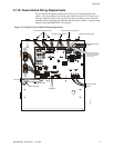
Note that relay connections may be power-limited or nonpower-limited, provided that
0.25” spacing is maintained between conductors of power-limited and nonpower-
limited circuits. Refer to UL Power-limited wiring requirements.
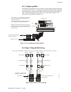
2.5 Notification Appliance Circuits
The control panel provides four Style Y (Class B) or two Style Z (Class A) NACs
(Notification Appliance Circuits). Each circuit is capable of 2.5 amps of current. Total
current in alarm for all external devices cannot exceed 6.0 amps (refer to "Calculating
the System Current Draw" on page 188). Use UL listed 24 VDC notification
appliances only. Circuits are supervised and power-limited. Refer to the Device
Compatibility Document for a listing of compatible notification appliances. The
NACs, which are located on the main circuit board, may be expanded via the FCPS
Series field charger/power supplies.
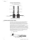
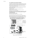
The following sections describe the configuration and wiring of Style Y and Style Z
Notification Appliance Circuits on the MS-9200UDLS main circuit board. The NACs
are configured for Style Y (Class B) from the factory. Refer to "Configuring NACs"
on page 51 for information on changing the NAC configuration to Style Z (Class A).
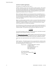
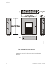
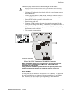
Figure 2.6 Relay Terminals
Relay contacts shown with power applied to panel and
no active troubles, alarms or supervisories
TB7
Note that the programmable relay labeled as
Relay 1 is factory default programmed as
Alarm and programmable Relay 3 is factory
default programmed as Supervisory.
The relay labeled Relay 2 is fixed as a
Trouble relay and cannot be changed. It is a
fail-safe relay which will transfer on any
trouble or total power failure.
92udreyp.cdr
TB5
TB6
Reference
Manual
See Page