


Installation
MS-9200UDLS PN 52750:E1 01/27/09 57
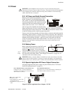
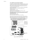
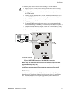
The following steps must be followed when installing the 4XTMF module:
1. Remove all power (Primary and Secondary) from the FACP before installing
4XTMF
2. Cut jumper JP3 on the main circuit board to allow the control panel to supervise
the 4XTMF module
3. Carefully plug the connectors on the 4XTMF module into connectors J5 and J6
on the MS-9200UDLS main circuit board, being careful not to bend any pins
4. Secure 4XTMF module to standoffs with supplied screws.
5. Reapply power to the FACP
6. For proper 4XTMF operation, the output relays must be programmed for the
factory default settings: Alarm Relay 1, Trouble Relay 2 and Supervisory Relay 3
7. When the installation has been complete, enable the 4XTMF module by sliding
the disconnect switch to the left
8. Test system for proper operation
NOTE: Jumper JP2 on the FACP main circuit board can be used to configure the FACP
supervisory relay for operation with the 4XTMF module. Relay 3 at TB5 must be
programmed as a supervisory relay.
Cutting JP2 will allow the 4XTMF to generate a trouble if the supervisory contact opens
Leaving JP2 in will prevent generation of a trouble if the supervisory contact opens
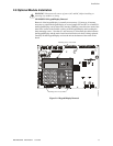
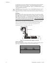
2.9.2 Printer
A serial printer may be connected to TB8 Terminals 1 - 4 on the FACP. The printer can
be used to provide a hard-copy printout of real-time events, history file and walktest
data. Installation the device requires panel programming to allow the FACP to
communicate with the device.
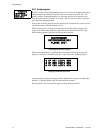
Figure 2.16 4XTMF Connectors to MS-9200UDLS Connectors
J5 & J6 Connectors
Cut Jumper JP3
Standoff Standoff
4XTMF
FACP main circuit board
92udls4xtm.cdr