


12 MS-9200UDLS PN 52750:E1 01/27/09
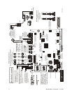
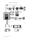
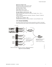
PS2 Keyboard Interface DACT Phone Line Jacks
(Nonpower-Limited)
Resettable Power - 24 VDC filtered, power-limited
(0.300 amps maximum) to smoke detectors (IDC).
Supervision required.
Nonresettable or Resettable Power
Jumper selectable by JP4, 24 VDC filtered,
power-limited (0.300 amps maximum)
Supervision required. Nonresettable
Power suitable for powering annunciators,
Resettable Power suitable for powering
smoke detectors..
NAC #1 & #2
Style Z (Class A)
2.5 amps max. per circuit.
JP6 configured for Class A
using NACKEY card.
(Supervised, Power Limited)
NAC #1
NAC #2
NAC #1, #2, #3 & #4, Style Y (Class B) (Supervised, Power Limited)
(Special Application) 2.5 amps max. per circuit. JP6 configured
for Class B using NACKEY card.
(See Style Z illustrated near right edge of board).
Nonsupervised relay contacts
Contact Ratings:
2.0 amps @ 30 VDC (resistive)
0.5 amps @ 30 VAC (resistive)
Contacts shown below in normal
condition (AC power with no alarm,
trouble or supervisory activity).
A Fail Safe Trouble
relay switches to the
NO position during
trouble conditions and
under loss of all power.
(nonsupervised)
For EDP-listed equipment or
personal computer with FACP
Upload/Download Utility.
50 foot maximum within same room.
(supervised)
Refer to the SLC Wiring
Manual for detailed
information on wiring
addressable devices
for Style 4, 6 and 7.
ACS/ANN-BUS
(EIA-485)
to Annunciators
(power-limited,
supervised)
ELRs 4.7K, ½W
Special Application DC Power Outputs (24 VDC)
Nonsupervised, power-limited circuits
Supervise with a power supervision relay A77-716B
Battery
Basic System Connections
Notification Appliance Circuits
Notification Appliance Circuits
2 Programmable Relays &
1 Fixed Trouble Relay
EIA-232
to printer or
personal computer
SLC Loop
OR
B
+
B
+
B
-
B
-
A
+
A
+
A
-
A
-
NO NC C NC NO CNO NC C
Alarm*
Trouble
Supervisory*
TB3
TB4
CAUTION! HIGH VOLTAGE
NC NO C
+
+
+
+
+
+
120 VAC, 60 HZ, 3.0 amps
24 VDC, supervised,
nonpower-limited
18 Amp Hour maximum
+ 24V -
NO N-RST
POWER
+ 24V -
RST
POWER
REMOTE PWR
SUPPLY SYNC NAC 1 CLASS A
NAC 1 & 3 CLASS B
NAC 2 CLASS A
NAC 2 & 4 CLASS B
RELAY 3
RELAY 1
HOT NEUT EARTH
- +
BATTERY
LCD DISPLAY
REMOVE TO
DISABLE GND. FLT.
CUT TO
MONITOR
4XTMF
KISSOFF
PRI. ACTIVE
SEC. ACTIVE
SEC. PHONE LINE
PRI. PHONE LINE
4XTMF
MINI DIN
KEYBOARD CONN.
KEYPAD
I/F
RELAY 2
TRANSFORMER 1
TRANSFORMER 2
+ -
B+ A+ A- B- B+ A+ A- B-
1 B + 3 B + 3 B - 1 B - 2 B + 4 B + 4 B - 2 B -
NO NC C
NO NC C NC NO C
B+ A+ B- A- A B
SHIELDSLCSLC
SLCSL C
IN+ IN- OUT+ OUT-
TB5
TB6 TB8 TB9 TB10
JP2
JP3
SW1
JP7
JP5
JP6
3
2
1
TB11
J10
J3
PH15 PH16
J7
J5
J1
J4
J9
J6
J11
CAUTION!
HIGH VOLTAGE
(* )Factory default relay programming
shield
B
+
B
-
BA
+
A
-
A
TERM
(EIA-485)
to LCD annunc.
I
N
-
I
N
+
O
U
T
+
+
-
Remove this jumper
to disable the FACP
battery charger when
using external charger.
Transformer 2 Connector
Transformer 1 Connector
Flash Memory Load Enable Switch.
UP is normal position for switch.
DOWN position allows loading of
factory software upgrades.
Cut this jumper to enable
Supervisory relay when
4XTMF module is installed
Cut this jumper to supervise
the 4XTMF module when
installed (see J5 & J6)
To disable ground fault detection,
remove jumper/shunt from JP7
Configure NACs for Class A or
Class B wiring using NACKEY
card. Factory default is Class B.
NAC #1 NAC #3
NAC
Number
-
++
+
+
B
+
B
-
1
1
B
+
B
-
33
NAC #4 NAC #2
B
+
B
-
++
++
++
B
+
B
-
2244
TB3
TB4 TB7
2
1
2
1
4
3
+ +
- -
TB1
TB2
JP4
+
-
+
+
Remote Synchronization Output
Special Application Power
24 VDC filtered, supervised and power-limited.
0.040 amps maximum, follows NAC1 control circuit.
Requires 4.7kohm End-of-Line resistor.
Important!
voids
only
Removing Ground
Fault Disable Jumper JP7
UL/NFPA Style/Class
identifications for circuits.
Remove jumper JP7
with the approval of the AHJ
(Authority Having Jurisdiction)
O
U
T
-
DB9F
OR
5 4 3 2 1
9 8 7 6
Green
Black
White
Red
T
X
R
C
V
TB8 (option to DB-25)
TB8
TB8
5 4 3 2 1
25 24 23 22 21 20 19 18 17 16 15 14
9 8 7 613 12 11 10
T
X
R
C
V
D
T
R
G
N
D
G
N
D
D
T
R
J12
USB Port J12 for local
programming using a
personal computer and
programming utility.
220/240 VAC, 50 Hz, 1.5 amps
92udLSlayo.cdr