


5-36 Pelco Manual C501M-B (10/97)
5.5.2.12 Programming Relay Follow
The System 8500 is capable of providing relay closures
through the use of the CM8532 Relay output card. These
relays can be energized manually or automatically
through alarm programing.
The CM8532 relay follow card provides 32 double-pole
outputs so that two contacts can be switched simulta-
neously per relay command. The programming is moni-
tor specific. A relay is commanded to energize based
on a specific camera input routed to a specific monitor
output. Relays can also be manually commanded to
energize/de-energize.
The System 8500 offers 32 assignable relays, allowing
for a relay follow table to be programmed for each moni-
tor. When a camera is selected to a particular monitor
(for any reason), a relay can be energized. This feature
is useful in enabling/disabling lighting, microphones,
speakers, triggering video cassette recorders, and other
uses.
NOTE: The CM8532 is not an audio matrix
(i.e., when attempting to route multiple audio
paths to multiple monitoring stations, you may
have serious audio problems if you attempt to
use this board). If you have questions regard-
ing the use of the CM8532 or relay program-
ming, please call the factory toll-free at
(800)289-9100.
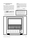
1. Select AlrmRel from the main menu bar (see
Figure 22).
2. Select Relay from the resulting drop-down menu.
3. From the Relay Follow table, select the moni-
tor camera/relay table to be edited.
4. Edit the monitor/camera assignment by selecting
the viewing monitor to trigger the relay (M1, M2,
M3...) from the Relay Follow menu box. When a
monitor is selected, the Relay Follow menu
box for assigning camera/relay will result.
5. Select the camera to be edited, and then select the
relay number of the camera and enter the desired
relay number (0 = no relay) from the keypad.
Note that the relay number will disappear as the
prompt waits for the relay number to be typed at
the keypad. The relay can be cleared by double
clicking on camera field.
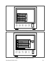
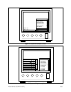
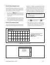
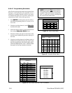
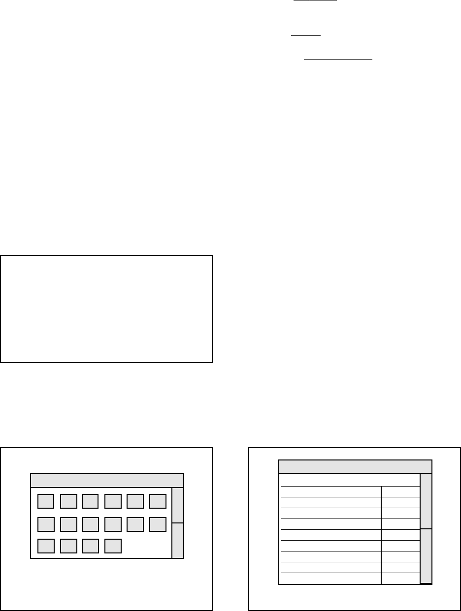
Figure 37. Relay Follow Assignments Menu
Relay Follow
Monitor Number:
Camera Relay
1
2
3
4
5
6
7
8
Use scroll bars to access all 32 camera/relay
follow assignments.
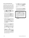
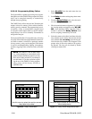
Figure 36. Relay Follow Menu
Use this menu to select the monitor camera/
relay table to be edited.
Relay Follow
M1 M2 M3 M4 M5 M6
M7 M8 M9 M10 M11 M12
M13 M14 M15 M16