


4-8 Pelco Manual C501M-B (10/97)
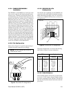
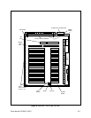
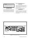
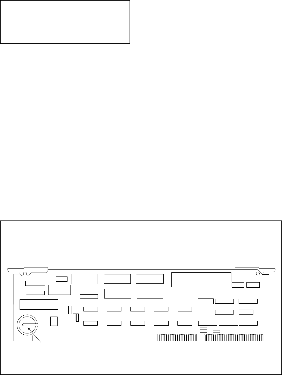
Figure 8. CPU Card Component Location
WARNING: To reduce the risk of personal
injury due to electrical shock and also to pre-
vent possible damage to the electronic circuitry,
always remove power to the unit prior to re-
moving or installing any printed circuit boards.
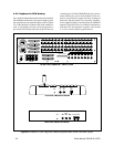
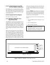
4.3.3.1.2 Insertion/Extraction of
the CM8504 I/O Card
Insert the CM8504 Input/Output card into the appro-
priate slot in the motherboard by grasping the white
handles, aligning the card with the card guides and push-
ing down firmly until the card seats in the edge con-
nector. To remove the card, lift up the ejector handles.
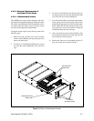
4.3.3.1.3 Insertion/Extraction of
the CPU Card
The CPU Card occupies the first slot (slot closest to the
backplane) in the motherboard. To install the CPU Card,
align the edge connector with the sockets and card
guides and press firmly into place. To remove the card,
lift up the ejector handles.
4.3.3.1.4 Insertion/Extraction of
the Buffer Card
The Buffer Card occupies the second slot (from the
backplane) on the motherboard. To install the Buffer
Card, align the card with the socket and card guides
and press firmly into place. To remove the card, lift up
the ejector handles.
Battery