


Pelco Manual C501M-B (10/97) 4-13
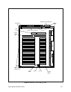
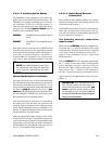
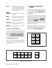
4.3.6 Installation/Connection of
CM8532 Alarm/Relay Interface
4.3.6.1 Alarm/Relay Interface Kit
Installation
The Alarm/Relay Interface Kit contains the Alarm/
Relay Interface Board (with ribbon cables attached)
and all hardware needed to secure the board and con-
nectors. The Alarm/Relay Interface Board mounts
onto the Backplane of the CM8502-1 or CM8503-1
Card Cage (refer to Figure 6).
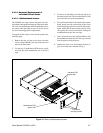
NOTE: To install the board, the top cover as
well as the CPU and buffer boards need to be
removed.
Connect the 10-pin connector from the Alarm/Relay
Interface board to the backplane of the matrix card cage.
Note that the connector is keyed and that the edges of
the connectors should match (i.e., that the connector
has not shifted over one way or the other).
Once connected, secure the Alarm/Relay Interface
Board to the standoffs with the hardware provided. Once
secured, remove the blank-off plate covering the con-
nector slots and mount the alarm and relay intercon-
nect ribbon cable connectors to the card cage. Refer to
the following information for the proper location of each
connector.
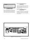
Alarm/Relay Interface Board Card Cage
P1 Relays Out 1-16
P2 Relays Out 17-32
P3 Alarms In 17-32
P4 Alarms In 1-16
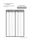
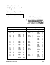
4.3.7 Alarm Input Connection
To connect alarm inputs to the system requires that the
alarm inputs first be wired into a 37-pin D-type con-
nector (supplied by Pelco). Refer to Section 4.3.7.1
for the connector pin designations. Once wired, con-
nect the connector to the appropriate location on the
back panel of the card cage.
4.3.3.4.3 Ground Loops
One other precaution to take prior to final connections
being made is to check all input coaxial cables for the
presence of possible ground loop voltages. Sync, video,
control functions, and/or system electronics may be ad-
versely affected by a ground loop condition. Call Pelco
if unable to correct any ground loop problems. Do not
connect cables to input connectors if ground loop volt-
ages are present between CPU and camera sites or be-
tween camera sites through the CPU. Pelco manufac-
tures the GIT100, ground isolation transformer, to help
alleviate ground loop problems in Coaxitron
®
-based
equipment. The use of fiber optics is also another means
to eliminate ground loops in a system.
4.3.3.4.4 Hookup
After ensuring that the above conditions have been met
and that all precautions have been observed, the co-
axial inputs from the camera locations can be connected
to the input connectors on the backplane of the card
cage.
Be sure that each connection is secure and that the con-
nectors are properly installed.
It is always good installation practice to mark or num-
ber all cabling. If system troubleshooting is necessary
and cables need to be disconnected, system downtime
can be minimized with a well organized cable identifi-
cation system.
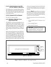
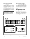
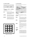
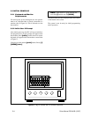
4.3.4 Connecting Keyboard to
the Data Monitor
Each keyboard will utilize a system monitor output for
programming and keyboard feedback. Select one moni-
tor output at the keyboard location to be the data monitor
and connect that output from the card cage to the key-
board video input connector. Connect the monitor output
from the keyboard to the appropriate monitor and ensure
correct termination (75 Ohm). Refer to Figure 10.
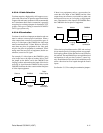
4.3.5 Connecting Other System
Monitors
All other system monitors may be interconnected to
the video output BNC terminal(s) of the card cage with
the appropriate length and type of coaxial cable or
fiber-optic interface equipment. The video output of
the CM8500 is a standard NTSC 1V p-p video signal.
Again, ensure for proper 75-Ohm termination at the
monitor(s) or other video processing equipment.