


Pelco Manual C501M-B (10/97) 4-7
4.3.3.1 Removal/ Replacement of
Individual Circuit Cards
4.3.3.1.1 Motherboard Access
The CM8500 card cage has been designed with user-
convenience and operational integrity foremost in mind.
The slide-out motherboard makes dependable electri-
cal contact while providing an easy-to-service system
for circuit board upgrade and replacement.
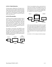
To upgrade and/or replace circuit boards, perform the
following steps:
1. Remove the four (4) front cover screws from the
corners of the CM8500 card cage front panel and
remove the front panel.
2. Use the two (2) motherboard PCB ejectors to pull
and slide the main motherboard out of the card
cage.
3. To remove an individual circuit board, pull up on
the metal ejector tabs. The card should easily slide
out of the card slots of the motherboard.
4. To install an individual circuit board on the mother-
board, gently press the contact edge of the circuit
board into the appropriate card slots on the mother-
board. Make sure the metal ejector tabs lay down
flat against the circuit board before sliding the
motherboard back into the card cage.
5. After all boards have been replaced/added, slide
the motherboard back into the card cage unit and
lock the ejectors back into place.
6. Replace the front cover and reattach the four (4)
grey screws that were removed in Step 1.
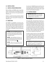
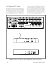
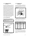
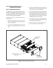
Figure 7a. Slide-out Motherboard Access
Motherboard PCB
ejector tabs
Individual PCB
ejector tabs
Front panel
mounting screws