


4-10 Pelco Manual C501M-B (10/97)
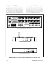
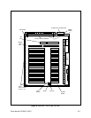
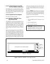
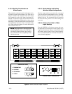
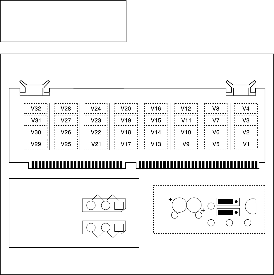
Figure 9. Buffer Card and Jumper Locations
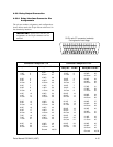
4.3.3.2 Setting Termination on
Video Inputs
The termination settings for the 32 video inputs are in-
dividually assigned on the Buffer Card. There are 64
jumpers located on the component side of the board,
two jumpers for each video input (designated V1
through V32). Refer to Figure 9. The board will have
to be removed from the motherboard in order to change
the setting(s). Follow the instructions for board removal
and replacement in Section 4.3.3.1.4 and refer to Fig-
ure 9 when setting the jumpers. For more information,
refer to Section 4.3.3.4.2.
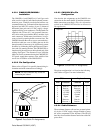
NOTE: Jumper positions 1 and 2 apply to the
terminating/looping status of the individual
video inputs. Jumper positions 3 and 4 apply to
the Coaxitron
®
/two-wire compatibility of the
individual receiver.
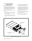
4.3.3.3 Determining and Setting
Monitor Output Assignments
Monitor output numbers automatically correspond
to the slot that the Input/Output board is installed.
The first monitor slot is the one just forward of the
Buffer Card slot. The last monitor slot is located in
the forward-most position. No other settings are
necessary.
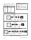
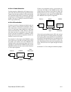
4.3.3.4 Camera Location to Video
Input Hookup
Since the CM8500 is a Coaxitron
®
system, each cam-
era input that has a Coaxitron
®
receiver requires only a
single coaxial cable (or fiber) to transmit both video
and camera control signals. Follow camera manufac-
turers’ recommendations for maximum allowable dis-
tances for their equipment.
SECTION 100
JUMPER SETTINGS
1 - TERMINATING
2 - LOOPING
3 - COAXITRON
4 - 2-WIRE
12
34
TYPICAL FOR V1 THROUGH V32