


Pelco Manual C501M-B (10/97) 4-9
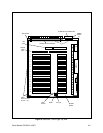
4.3.3.1.5 Installing Option Boards
The CM8500 is factory-equipped as a Coaxitron com-
patible only system (unless requested differently). The
CM8500 is also capable of transmitting two-wire con-
trol information in RS-422 or Wiretron formats. To
make use of the system’s two-wire capabilities, the ap-
propriate Pelco CM8500 Option Board must be
installed to the system buffer board.
CM8506 CM8500 Wiretron compatible option
board
CM8507 CM8500 RS-422 compatible option
board
Both option boards install into the CM8500 system
using the same procedures. It is important to note that
only one option board can be installed, making the sys-
tem either Coaxitron
®
/Wiretron compatible or
Coaxitron
®
/RS-422 compatible. The system cannot
work with all three information formats at the same
time.
NOTE: The CM8506/CM8507 option boards
are transmit-only units. Only the appropriate
control signals are generated from the option
boards.
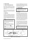
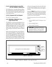
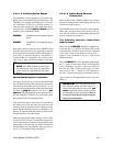
Option Board Physical Installation
The option boards are easy to install and should take
only a minimum of time. After turning off system power
and removing the buffer board (see section 4.3.3.1.4),
notice on the un-populated side of the buffer board there
are three (3) plug-in connectors and five (5) hex
spacers. The populated side of the option board (ei-
ther the CM8506 or CM8507) has the matching male
pin connections and five mounting holes.
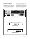
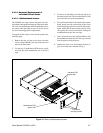
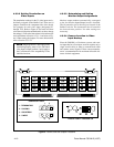
Line the female plug-in connectors and standoffs on
the buffer board with the male pin connectors and
mounting holes on the option board. Gently press the
boards together making the plug in connections. Use
the five (5) supplied mounting screws to firmly secure
the option board to the buffer board.
Make the appropriate jumper settings on the buffer
board (each receiver that is compatible with the new
option board must have jumpers set on the buffer board
appropriately). Reinstall the new buffer board/option
board assembly into the CM8500 card cage. See sec-
tion 4.3.3.2 for jumper setting information.
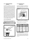
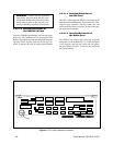
4.3.3.1.6 Option Board Receiver
Connections
When working with CM8500 optional data formats,
keep the following in mind when making the two-wire
connections to the receivers.
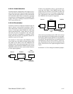
The CM8500 system offers no receiver addressability.
Home runs are required for each receiver in the sys-
tem, and each receiver (if addressability applies to the
receiver) must be set to address 1.
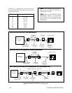
The following two-wire connections
must be made:
When using the CM8506 Wiretron compatible op-
tion board, the “+” output for the camera that is to be
controlled with a Wiretron receiver must be connected
to the “high” input on the Wiretron receiver. The “-”
output is to be connected to the “low” input on the
Wiretron receiver.
With the CM8507 RS-422 compatible option board,
the “+” output for the camera that is to be controlled
with an Intercept
®
or Legacy
®
receiver is to be con-
nected to the “RX+” input on the Legacy
®
or Inter-
cept
®
receiver. The “-” output is to be connected to
the “RX-” input on the Legacy
®
or Intercept
®
receiver.
Again, make sure all addressable receivers are set to
address 1.
IMPORTANT: After the Option Board has
been installed, and the individual jumper se-
lections have been made for each receiver, you
must program the system software to match
the individual receiver data formats. Refer to
Section 5.5.2.4 for Receiver Types Program-
ming Screen information.