


4-2 Pelco Manual C501M-B (10/97)
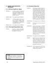
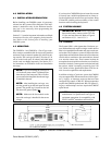
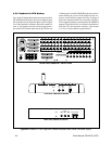
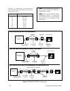
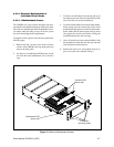
Figure 2A. CM8503-1 Card Cage and CM8505 Keyboard Back Panel Connector Layout
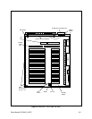
REAR VIEW CM8503A-1 CARD CAGE
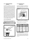
4.3.2 Keyboard to CPU Hookup
Up to eight (8) independent keyboards may be installed.
The backplane of the main card cage has eight (8) ports
that correspond to the keyboard inputs (refer to Figure
2A). If the supplied 8-conductor flat cable assembly is
used, it only requires that one end be plugged into a
port on the CPU and the other into the port on the rear
of the keyboard. (On the CM8505R keyboard, it doesn’t
matter which port you use on the keyboard. Two con-
nectors are provided to support the daisy chaining of
keyboards, but this feature is not currently available.)
If user-supplied cabling is installed, then the CM9505J
adapter kit should be used to facilitate installation at
both the CPU and keyboard locations. (See Section
4.3.2.4 for wire-run distance specifications.)
RELAYS OUT 1-16
FUSE 3AG (5X20)
250V 2A
RELAYS OUT 17-32
ALARMS IN 1-16
ALARMS IN 17-32
1357
2468
KEYBOARDS
TWO WIRE CONTROL 1-16
TWO WIRE CONTROL 17-32
EXTERNAL VIDEO IN
4 6 8 10 12 14 16 18 20 22 24 26 28 30 32
35791113151719212325272931
2
1
1357911
13 15
24681012
14 16
VIDEO INPUTS
VIDEO OUTPUTS
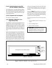
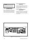
REAR VIEW, CM8505D KEYBOARD
RESET
VIDEO
OUT
VIDEO
INPUT
DATA
PORT
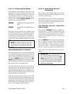
REAR VIEW, CM8505R KEYBOARD
LOOPING
VIDEO
OUT
VIDEO
OUTRESET
VIDEO
INPUT PWR/COM PWR/COM