


4-6 Pelco Manual C501M-B (10/97)
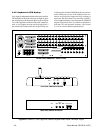
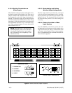
LED will be illuminated. The Power On LED, when
on, indicates the unit On/Off switch is in the On posi-
tion. The +5 VDC LED indicates the power supply is
operating.
Pressing the Reset button while the unit is operating
will cause the system to initialize and restart operation.
This is the same as cycling power. Pressing the SFT
CLR (Software Clear) button during normal operating
conditions does not affect operation.
The following procedure will erase all user-programmed
memory:
1. Hold in the RESET and SFT CLR buttons for five
seconds.
2. Release the RESET button.
3. Release the SFT CLR button.
CAUTION: Cycling power with the SFT
CLR button pushed will erase all user-
programmed memory. (Pressing the RE-
SET button is the same as cycling power.)
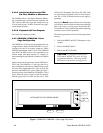
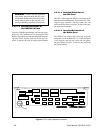
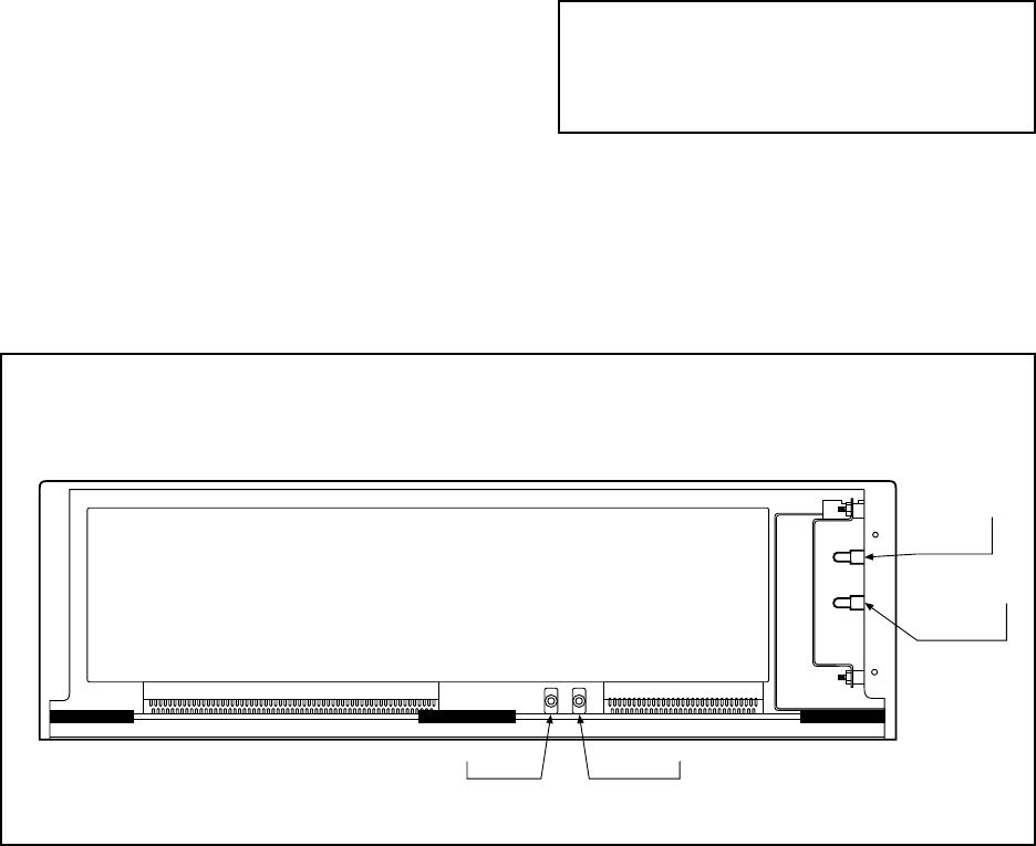
Figure 7. CM8502A-1/CM8503A-1 Card Cage Front View
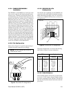
4.3.2.5 Interfacing Keyboard to CPU
Via Fiber, Modem or Microwave
The CM8500 utilizes a full duplex balanced differen-
tial communications scheme between keyboard and
CPU, similar to RS-422 except that voltage levels are
10 volts peak to peak. Call Pelco if there are any appli-
cation related questions.
4.3.2.6 Keyboard Self-Test Program
This option not currently available.
4.3.3 CM8502A-1/CM8503A-1 Card
Cage Configuration
The CM8502A-1 Card Cage may be configured for one
to eight monitor outputs and the CM8503A-1 may be
configured for one to 16 monitor outputs by adding
CM8504 Input/Output Matrix Cards. Each CM8504
card allows the 8500 system to be expanded by one
monitor output. The input capacity (32 cameras) re-
mains unchanged by the addition or deletion of CM8504
cards.
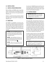
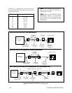
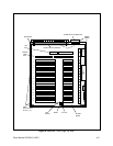
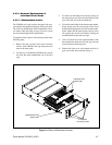
Figure 6 shows the board location for the CM8503A-1
Card Cage. The CM8502A-1 Card Cage board loca-
tions are identical, with the only difference being eight
(8) fewer video input/output slots. (Slots 9-16 are not
present in the CM8502A-1 version.) Refer to Figure 7
for the front view of the CM8502A-1/CM8503A-1 Card
Cages. When the power switch is in the On position,
both the green Power On LED and the red +5 VDC
VIDEO INPUT/OUTPUT MATRIX CARDS
+5 VDC
LED
PWR ON
LED
RESET SFT CLR