


Pelco Manual C501M-B (10/97) 4-3
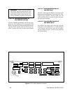
4.3.2.1 CM9505UPS/CM9505J
Installation
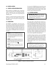
The CM8502A-1 and CM8503A-1 Card Cages each
offer a total of eight (8) individual keyboard commu-
nications ports. Normally one keyboard utilizes one
communications port. Communications between each
keyboard and the CPU consists of two (2) balanced
differential data pairs and ±12 VDC supply voltages
together utilizing seven conductors. The keyboards are
supplied with 25-foot (63.5 cm) pretested intercon-
nect cables with pre-assembled RJ-45 modular 8-pin
male connectors. Within many installations, it is nec-
essary to install system keyboards at remote sites. The
CM9505J Junction Box allows you to convert the key-
board data cable into a set of cabling that can be run
through conduit (if necessary) for significantly greater
distances by eliminating the keyboard power connec-
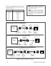
tions and only running the data. The CM9505UPS re-
introduces keyboard power at the keyboard end of the
cabling. See Figure 5. For distances of over 2,000 feet
(609.6 m), Pelco recommends using the CM9505UPS-
422 power supply/data repeater at the middle of the
run of wire in addition to the CM9505UPS.
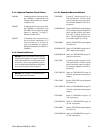
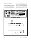
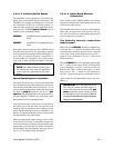
4.3.2.2 Pin Configuration
Please refer to Figure 3 for specific pinout/wiring in-
formation and make connections accordingly.
NOTE: For data connection only, do not use
connection pins 3 thru 6.
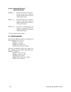
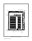
Figure 3. Data Cable Pin Assignments
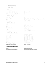
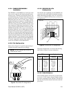
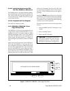
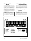
Figure 4. Junction Box Pin Assignments
CPU Keyboard
Pin# Function Function Pin#
1 Data in + Data out + 1
2 Data in - Data out - 2
3 -12 VDC -12 VDC 3
4 +12 VDC +12 VDC 4
5 Ground Ground 5
6 Spare Spare 6
7 Data out - Data in - 7
8 Data out + Data in + 8
1
2
3
6
7
8
5
4
PR 4
PR 2
PR 3 PR 1
Pin 8
Pin 1
Top View
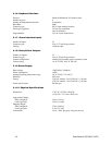
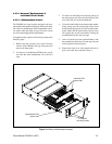
4.3.2.3 CM9505J Wire/Pin
Configuration
Note that the pin assignments on the CM9505J wire
connection do not match the RJ-45 modular connector.
Make connections accordingly. (The color information
printed on the CM9505J PC board has no relevance in
this application.)
The pinout configuration is as listed on the following
table. Refer to Figure 3 for more information.
4.3.2.4 Cable Distances
The maximum distances allowed are governed prima-
rily by the 12 VDC supply voltages needed to power
the active components of the keyboard. The RS-422
data lines far exceed the distance restrictions of the DC
power lines.
Pin 1
Pin 8
12345678