


Pelco Manual C501M-B (10/97) 4-1
4.0 INSTALLATION
4.1 INSTALLATION PREPARATION
Before installing your CM8500 system, it is necessary
to know how the system will be configured. This infor-
mation is needed not only for the hardware installa-
tion, but is also necessary when programming the
CM8500 system.
Section 5.5.1 contains important information and blank
forms that will assist you in preparing for the installa-
tion. Refer to this section prior to installing your
CM8500 system.
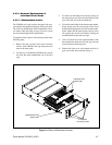
4.2 MOUNTING
The CM8502A-1 and CM8503A-1 Card Cage assem-
blies come pre-assembled with all circuit cards installed
and tested, ready to mount in standard 19-inch EIA rack-
ing consoles. The card cage will take 5.25 inches (13.34
cm) of vertical rack space. If ordered, individual spare
circuit cards are shipped separately. See Section 4.3.3
for instructions on individual circuit card installation
and setup.
NOTE: If you are installing the card cage in
a 19-inch rack, remove the 6-32 flathead screw
from the top of the front panel. This will allow
you to remove the front panel after the card cage
is installed in the rack.
NOTE: After installing the card cage, con-
nect the ground lug on the back panel to earth
ground. The ground lug is located on the left
side above the ground symbol .
NOTE: Make sure the fuse module on the
rear of the card cage is installed for the correct
voltage.
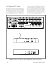
If you have the CM8505R keyboard controller, mount
it securely into a suitable equipment rack or frame, us-
ing the supplied rack mount screws and washers. Keep
in mind the visibility and accessibility of the control
functions while installing the keyboard.
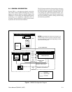
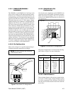
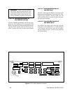
4.3 SYSTEM HOOKUP
IMPORTANT NOTE: Remove the paper
between the battery contacts on the CPU card
if it has not been removed. Refer to Figure 8
and Sections 4.3.3.1.1 and 4.3.3.1.3.
4.3.1 General
The System 8500 is a third-generation Coaxitron
®
sys-
tem, and therefore only requires a single coaxial cable or
fiber* to be installed from the main card cage to each cam-
era location. The Coaxitron
®
system will receive the video
signals from each individual camera and will use the same
coaxial cable to send data to the receiver/drivers located
at or near the camera sites. Fixed camera locations do
not require the receiver/driver unless the use of auxiliary
functions is desired. Camera power can be derived from
the receiver, which is normally powered by local 120
VAC. Refer to Pelco Specification Sheet C550 for de-
tails of receiver capabilities and requirements.
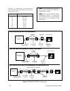
In addition to being a Coaxitron
®
system, the CM8500
also can support Pelco Wiretron receivers or Pelco Spec-
tra™, Legacy
®
or Intercept
®
receivers that have been
configured for control via RS-422. Wiretron operation
requires the CM8506 option board; RS-422 Spectra™,
Legacy
®
and Intercept
®
receivers require the CM8507
option board.
* NOTE: Check with your fiber-optic equipment
manufacturer for specifications and type of
equipment appropriate for compatibility with
Pelco Coaxitron
®
transmitters and receivers.
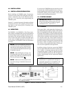
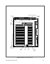
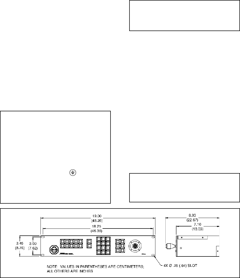
Figure 2. CM8505R Dimension Drawing