


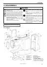
9. DISASSEMBLY
KE-430F, BE-438F
66
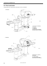
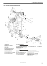
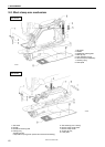
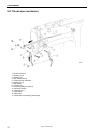
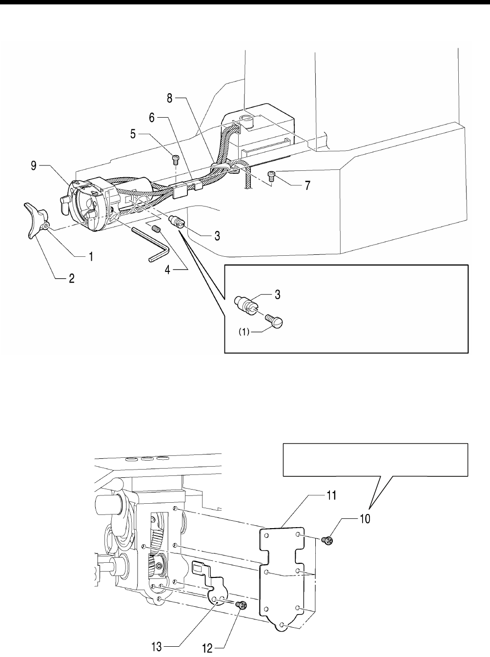
9-5. Lower shaft mechanism
(Continued on next page.)
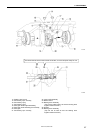
10. Screws [5 pcs]
11. Gear cover
12. Screws [2 pcs]
13. Positioning plate
2541B
Do not remove the gear cover if at all
possible, otherwise grease will leak out.
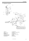
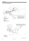
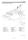
1. Bolt [Loosen]
2. Driver
3. Adjusting stud [Pull out]
4. Set screw [Loosen]
5. Screw
6. Oil tube support
7. Screw
8. Cord holder U3
9. Shuttle race base assembly
2540B
If the adjusting stud 3 will not pull
out, screw a M3 or similar screw (1)
into the tap hole and then pull on the
M3 or similar screw (1) so that the
adjusting stud 3 can be removed.