


15. ELECTRIC MECHANISM
151
KE-430F, BE-438F
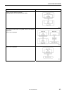
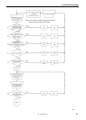
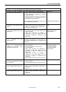
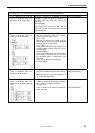
Error status #2 Error code appears on the display when the power is turned on.
Probable causes Check/ repair/ adjust Parts to be replaced
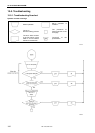
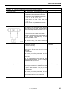
1. If “E025” or “E035” is displayed,
the foot switch is still depressed.
a. Check if the foot switch is still depressed.
b. Check if there is a short-circuit in the harness.
c. Check if connector P12 (PEDAL) is connected
to the motor PCB.
d. Reset the depression stroke for the foot switch
while referring to “11-22. Standard setting for
depression stroke (foot switch)”.
* For a 2-pedal foot switch, the connector for the
main PCB will be P15 (PEDAL).
Treadle unit
2-pedal foot switch assembly
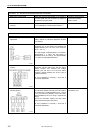
2. If "E055" is displayed, there is a
malfunction of the machine head
switch.
a. Check if the machine head switch is off.
b. Check if there is a broken wire in the harness.
c. Check if connector P14 (HEAD-SW) is
connected to the main PCB.
Switch assembly machine
head
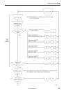
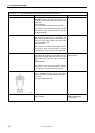
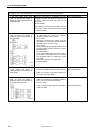
3. If "E065" is displayed, one of the
keys on the operation panel is still
depressed.
a. Check that there is no incorrect sensitivity
when the surface of the panel sheet and the
keys are pressed.
b. Check that connector P3 (PANEL) is
connected to the motor PCB, and that
connector P1 (MAIN) is connected to the
panel PCB.
Operation panel assembly
Panel PCB assembly
Panel harness
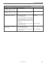
4. If “E131” is displayed, there is a
poor connection of the
synchronizer.
Check that connector P11 (RESOLVER) and P1
(MT-ENC) is connected to the motor PCB, and
that connector P6 (MT-ENC) is connected to the
main PCB.
5. If "E400" and "E401" is displayed,
there is a connection fault
between the main PCB , motor
PCB and the panel PCB.
a. Check LD3 (green) on the main PCB.
OK if illuminated.
b. Check LD3 (green) on the motor PCB.
OK if illuminated.
c. Check that connector P5 (MOTOR) is
connected to the main PCB, and that
connector P2 (MAIN) is connected to the
motor PCB.
d. Check that connector P3 (PANEL) is
connected to the motor PCB, and that
connector P1 (MAIN) is connected to the
panel PCB.
e. Check if there is a broken wire in the harness.
Main PCB assembly
Motor PCB assembly
Panel PCB assembly
Connection harness
Panel harness
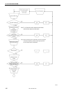
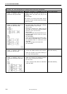
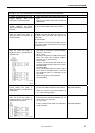
6. If "E450" or "E452" is displayed,
the machine head memory cannot
be recognized.
a. Check if connector P3 (HEAD-M) is connected
to the main PCB.
b. Check if there is a broken wire in the harness.
7. If "E700" is displayed, the power
supply voltage is abnormally high.
a. Check that the power supply voltage at the
mains is at the specification voltage plus or
minus 10%.
b. See #1-2.
8. If "E705" is displayed, the power
supply voltage is abnormally low.
a. Check that the power supply voltage at the
mains is at the specification voltage plus or
minus 10%.
b. See #1-2.