


8. MECHANICAL DESCRIPTIONS
KE-430F, BE-438F
55
8. MECHANICAL DESCRIPTIONS
* <number> and [number] indicates the flow of each operations given.
* (number) indicates part names only. (They do not represent the flow of operations.)
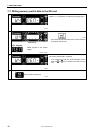
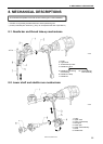
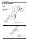
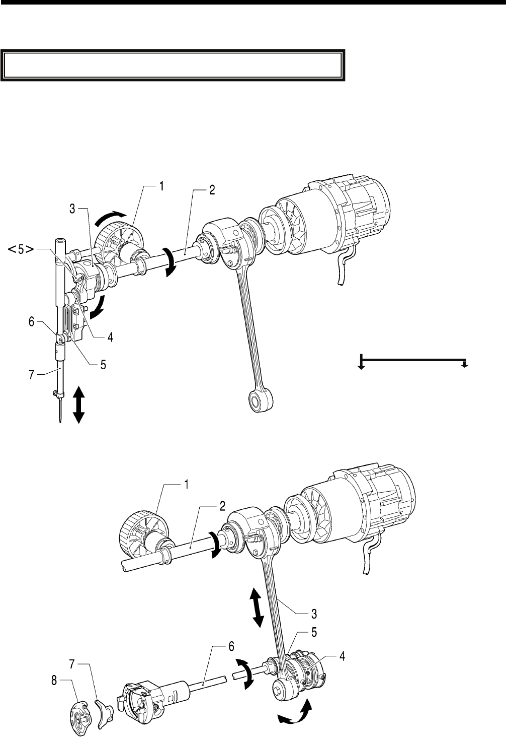
8-1. Needle bar and thread take-up mechanisms
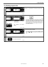
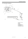
8-2. Lower shaft and shuttle race mechanisms
2524B
The mechanisms operate in the order of the numbers given in the illustrations.
1. Pulley
2. Upper shaft
3. Thread take-up crank
4. Needle bar crank
5. Needle bar connecting <5> Thread take-up
rod assembly lever assembly
6. Needle bar clamp
7. Needle bar
2523B
1. Pulle
y
2. Upper shaft
3. Crank rod assembly
4. Rock gear
5. Lower gear
6. Lower shaft assembly
7. Driver
8. Shuttle hook