


10. ASSEMBLY
KE-430F, BE-438F
90
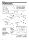
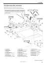
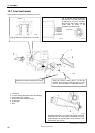
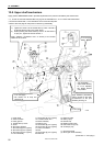
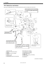
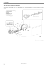
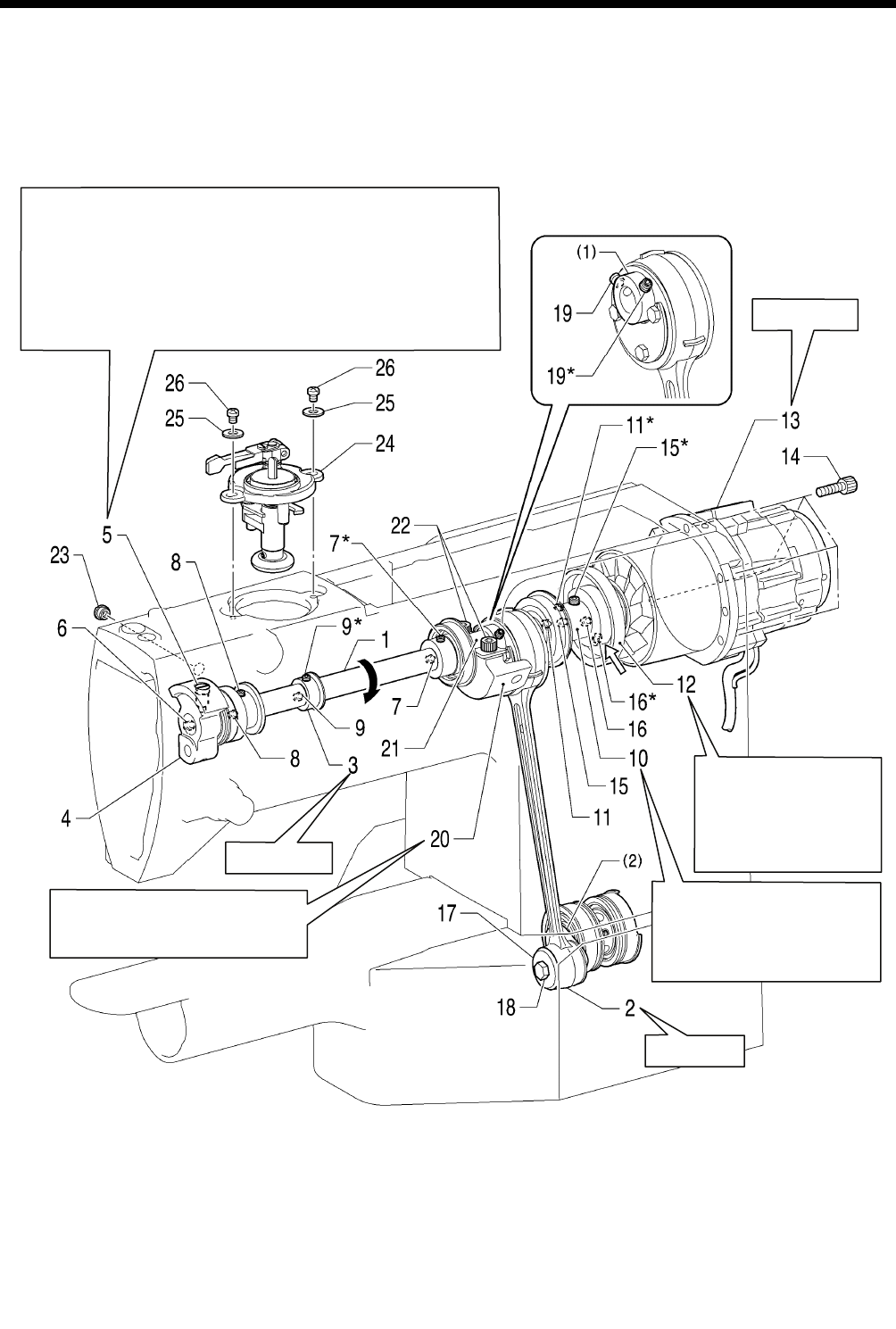
10-8. Upper shaft mechanism
Apply grease <GREASE BZL-300P> specified by Brother to the portions indicated by the white arrows.
* 17, 18 and 19 should be installed after carrying out the installations in “10-10. Lower shaft mechanism”.
* Set screws marked with * in the illustration are on the screw stop side.
* Refer to the next page for the points to note during reassembly.
(Continued on next page.)
1. Upper shaft
2. Crank rod base
3. Pulley gear R
4. Thread take-up crank
5. Screw
6. Set screw [Tighten]
7. Set screws [2 pcs: Tighten]
8. Set screws [2 pcs: Tighten]
9. Set screws [2 pcs: Tighten]
10. Joint assembly
21. Balancer plate
22. Bolts [2 pcs]
23. Rubber cap
24. Bobbin winder unite
25. Plain washers [2 pcs]
26. Screws [2 pcs]
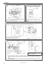
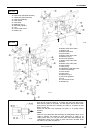
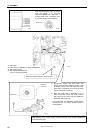
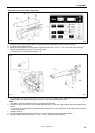
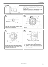
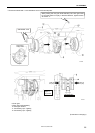
1) Tighten the screw 5 of the thread take-up crank 4 so that it
is aligned with the hole in the upper shaft 1.
2) While pressing the thread take-up crank 4 so that there is
no play in it, tighten the two set screws 7.
Apply adhesive (Threebond 1401 or similar) to the thread
section of the screw 5.
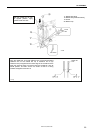
Apply adhesive (Threebond
1324 or similar) to the outer
circumference of the joint
assembly bearing 10.
・ A on next page
・ Adjust while referring
to “11-14. Adjusting
the thread trimmer
cam position”.
・ D on next page
・ Be careful not to drop the
balancer 20.
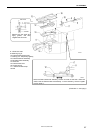
11. Set screws [2 pcs: Tighten]
12. Thread trimmer cam
13. Motor assembly
14. Bolts [4 pcs]
15. Set screws [2 pcs: Tighten]
16. Set screws [2 pcs: Tighten]
17. Crank rod washer
18. Bolt
19. Set screws [2 pcs: Tighten]
20. Balancer
(1) Eccentric wheel
(2) Rock gear shaft assembly
2860B
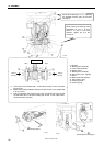
C on next page
B on next page
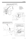
E on next page