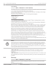
For example, if the necessary wait time is 30 sec, digits 14 through 16 should be 0, 3, 0
respectively.
In larger installation sites using alternate communications as a destination, set the wait time
to a higher value to compensate for network congestion delays. This wait time is also used for
the heartbeat acknowledge wait time. This is calculated using the following formula:
Value = (D14 X 100 + D15 X 10 + D16), where DXX is a digit number from the table entitled IP
address digit or bit location, 79. If the programmed value exceeds 255, it is read as 255.
A time-out on an alternate communication path is treated the same way as a negative
acknowledgement and results in the same event routing default scheme used with phone
reporting to the central station. This allows alternate communications to be the primary or
secondary reporting paths to an actual phone number for a single reporting destination.
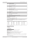
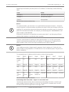
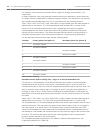
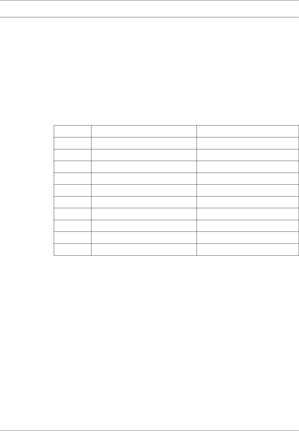
For the alternate communications path, see the following table:
Attempt
Primary phone line (phone 1) Secondary phone line (phone 2)
1 1st phone number
2 2nd phone number
3 1st phone number
4 2nd phone number
5 2nd phone number
6 1st phone number
7 1st phone number
8 2nd phone number
9 2nd phone number
10 1st phone number
Table 8.6: Phone reporting
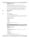
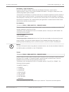
Heartbeat Interval (HB) or Polling Time – Digits 17 to 19, Recommended: 240
This interval is a value between 1 and 255 that indicates the number of seconds between
heartbeat events sent from the control panel. The heartbeat event is sent only when the
communication path is idle for at least the programmed heartbeat interval period of time. The
value is stored in phone number digits 17 through 19 with 17 being the most significant or
first digit. A value of zero in these locations disables the heartbeat feature. These digits are
always zero in the remote programmer phone number. Use the following formula to calculate
this value:
Value = (D17 x 100 + D18 x 10 + D19), where DXX is a digit number from the table entitled IP
address digit or bit location, 79. If the value programmed exceeds 255, it is read as 255.
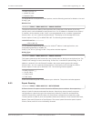
The heartbeat feature is an acknowledged test event sent to the central station receiver over a
network connection. This event does not appear at the central station, and it is not logged in
the control panel as an actual event. The heartbeat event is used as a periodic test of the
virtual circuit between the control panel and the networked receiver. The heartbeat event is
transmitted as a null‑Modem IIIa
2
event that uses only the first four digits of the account code
for Area 1. The event format always remains the same regardless of the communication
protocol formats available in the control panel.
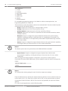
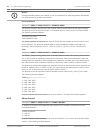
For acceptable programming selections for UL864 9
th
edition Listed applications, see
Programming features for UL864, 49.
80
en | Control Panel Programming Fire Alarm Control Panels
2012.08 | 04 | F01U008458 Installation and Operation Manual Bosch Security System, Inc.


