


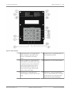

5. Show Status: After you select a device and press [#/Enter], this test shows detailed
status information for the selected device. Eight conditions (not all status conditions
apply to or are supported by all devices) are shown. See the display shown below (which
updates automatically every five seconds). For this option, you can view the status of any
MUX device regardless of which bus you selected to test when test mode was entered.
– XxLxRxDxMxTxFxAx
x is either 0 or 1 depending on whether the condition is false or true (0=false and 1=true). The
letters indicate the condition:
– X: Reserved for future use.
– L: Commanded relay state - this is how the output relay should be set. R: Actual relay
state - this is how the output relay is actually set.
– D: Detector dirty - the detector is excessively sensitive.
– M: Missing device - the device cannot be found on the loop. Unless a device was
programmed into the system (such as using MUX EDIT), it is not considered missing.
– T: Tamper – the detector’s case was opened.
– F: Loop fault - the loop from a contact input device is open, or the device is faulted. A:
Loop alarm - the point is in alarm.
Pressing [*/Back] ends the display for any of these modes.
Examples: X0L0R0D0M0T0F0A0 (relay off, not dirty, not missing, no tamper, no fault and no
alarm).
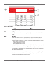
Sensitivity test
Tests the MUX smoke detectors to determine if they are within their normal range of
sensitivity. Press [Test] then [9].
Point/Zone Mapping
The control panel supports a flexible system to map input points to output points. The system
defaults so that all NAC outputs are activated by a fire alarm. By programming output zones,
you can create almost any output activation scheme, such as “floor above and floor below”
activation or conditional elevator recall.
Input points: Smoke detectors, pull stations, and so on.
Zone: A group of input points (Zones 1 to 50 are configurable, 52 to 63 are activated
automatically).
Output points: NACs (notification appliance circuits) such as bells, strobes, and relays. Inputs
activate zones, and zones activate outputs.
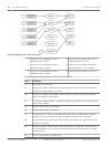
Zones 1 to 50 are available for the installer to program. Each input can activate one zone;
however, any number of inputs can be mapped to the same zone.
Zones above 50 are automatically activated by inputs. For example, any input that is
configured as a waterflow type activates Zone 61 when it is alarmed. Any output driven by
Zone 61 activates when any waterflow type point is alarmed.
Up to 64 zones can be assigned. The installer can assign Zones 1 to 50. Zones 51 to 63 are
hard-coded to pre-assigned conditions.
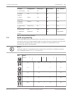
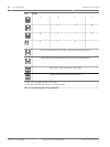
For how inputs control zones and zones control outputs, see the following figure:
6.4.7
6.5
Fire Alarm Control Panels System Operation | en 45
Bosch Security System, Inc. Installation and Operation Manual 2012.08 | 04 | F01U008458