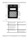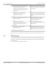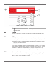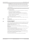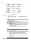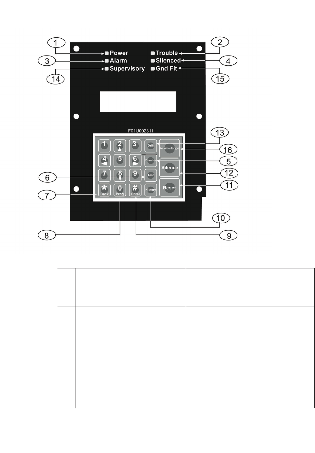
Figure 6.1: Built-in Keypad
1 Green Power LED - is on when the AC
power is present, and flashes when
the unit is operating from battery
power.
9 [#/Enter] key - to accept data when in
the programming mode.
2 Yellow Trouble LED - lights when the
system detects a problem with wiring
or internal circuitry. The Trouble LED
flashes while programming mode is
active and whenever inputs are not
active, such as during smoke power
reset or alarm verification.
10 [History] key - to view system events.
3 Red Alarm LED - lights when the
system registers an alarm and was not
reset.
11 [Reset] key - briefly (programmable
from 1 to 16 seconds) turns off power
to the detectors to reset them and
clears any off- normal conditions.
Fire Alarm Control Panels System Operation | en 41
Bosch Security System, Inc. Installation and Operation Manual 2012.08 | 04 | F01U008458


