i
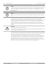
Notice!
This test is available only if your system sends alarms and system information to a monitoring
service, and was programmed by the security installing company to permit communicator
tests.
NOTICE!
!
Warning!
Reset upon termination of test
Terminating the communicator test function (with the [*/Back] key) resets the communicator
and discards all unsent reports. When an off-normal condition occurs during a Communicator
test, the test automatically resets, clearing all reports, so the off-normal conditions are sent
normally.
Battery/NAC circuits test
If a power failure occurs, your control panel has a built-in battery that continues to power the
system for several hours. The control panel automatically recharges the battery when power is
restored. In this test mode, the system operates the local NAC circuits and tests the battery
for two seconds. The test results are shown at the end of the test, and are not reported to the
central station. Pressing the [*/Back] key or the [#/Enter] key returns the display to standby
mode, or the unit times out after three minutes.
Activate ouputs test
This test turns a selected output on and off manually.
Zone input level test
This test shows the status of a selected on-board point. The loop existing through the point is
shown. Normal loops show 11 mA to 15 mA. Loops in alarm show over 25 mA, and loops in
trouble show less than 6 mA.
Addressable point test (MUX test)
This test allows activation of the special test mode for addressable (multiplex) devices. This
applies only if the optional D7039 Addressable Point Bus Expander module is installed. When
this test mode is selected, the system asks which bus to test, 1 or 2. Select 1 to test points 9
to 128 and select 2 to test points 129 to 255. The system presents 5 options:
1. List Devices: Shows the point numbers of all devices on the selected bus. Some devices
(such as a dual point module) can use two or more points
2. Show Holes: Lists locations on the bus that have no assigned device. This can help to find
programming errors or identify an available address for a new device.
3. Show Extras: The system scans the bus to identify devices that are present on the bus,
but are not programmed into the system. Scanning the bus takes about 60 sec. Restoring
the bus after scanning also takes about 60 sec. The system cannot identify devices above
Address 128 on Bus 1, or below Address 129 on Bus 2. If you know that a device is
connected to the system but cannot find it, ensure that it is connected to the correct bus:
9 to 128 for Bus 1, 129 to 255 for Bus 2.
4. Show Missing: Lists devices programmed into the system but not present on the bus are
listed. Unless a device was programmed into the system (such as using MUX EDIT), it is
not considered missing.
6.4.3
6.4.4
6.4.5
6.4.6
44 en | System Operation Fire Alarm Control Panels
2012.08 | 04 | F01U008458 Installation and Operation Manual Bosch Security System, Inc.


