Teledyne API Model T360/T360M Operation Manual Operating Instructions
69
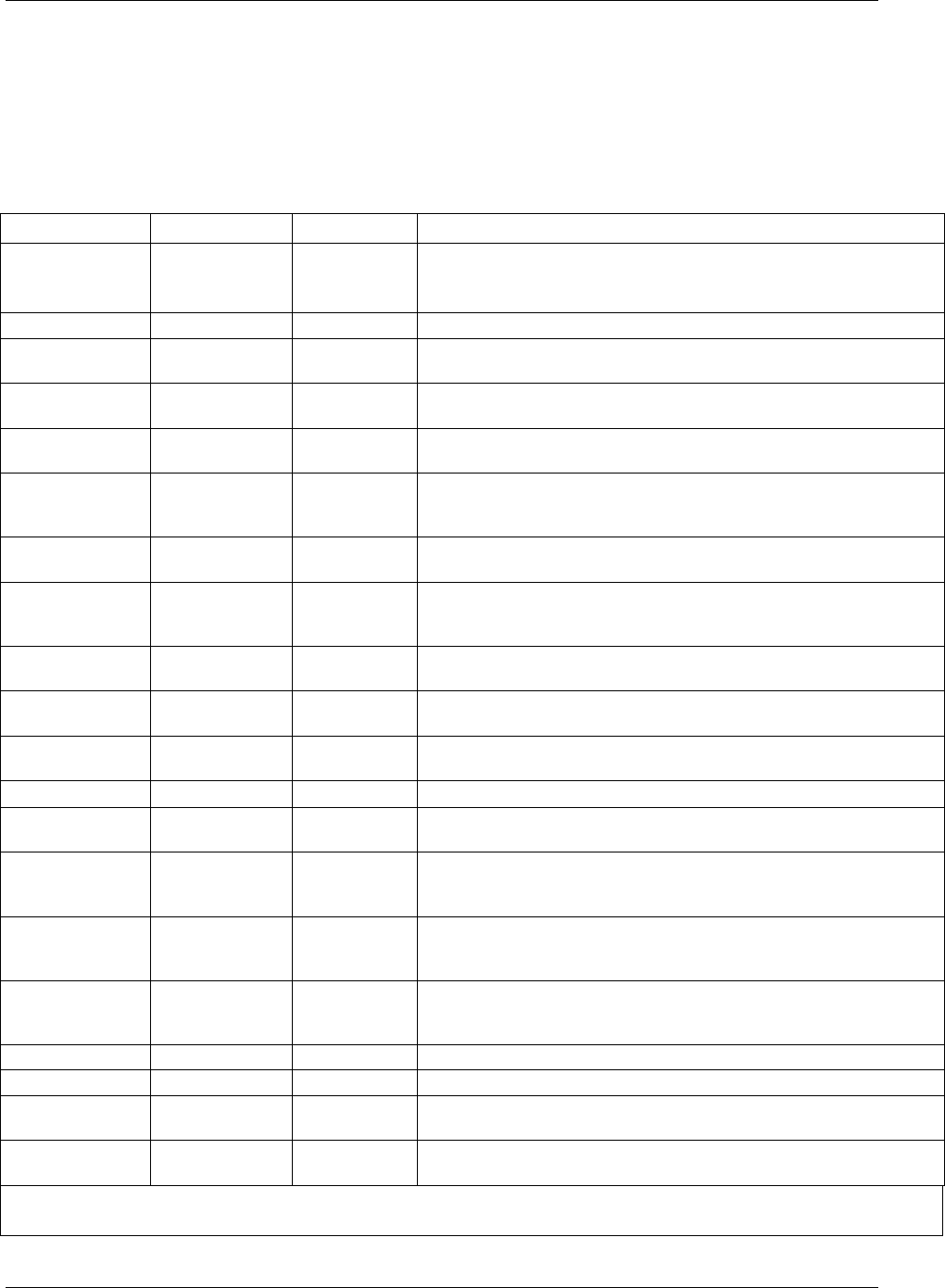
4.2.1. Test Functions
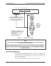
Test functions are shown on the front panel display while the analyzer is in
SAMPLE mode. They provide information about the present operating status of
the instrument and can be used troubleshooting and can be recorded in one of the
DAS channels (Section 4.7) for data analysis. To view, press <TST or TST>.
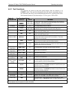
Table 4-2: Test Functions Defined
PARAMETER DISPLAY UNITS MEANING
Range
RANGE
RANGE1
1
RANGE2
1
PPB, PPM,
UGM, MGM
The full scale limit at which the reporting range of the analyzer is
currently set. THIS IS NOT the Physical Range of the instrument.
See Section 4.8 for more information.
O
2
Range
O2 RANGE
% The range setting for the O
2
Sensor
Stability
STABIL
PPB, PPM
UGM, MGM
Standard deviation of CO
2
concentration readings. Data points are
recorded every ten seconds using the last 25 data points.
CO
2
Measure
MEAS
MV
The demodulated, peak IR detector output during the measure
portion of the GFC Wheel cycle.
CO
2
Reference
REF
MV
The demodulated, peak IR detector output during the reference
portion of the GFC wheel cycle.
Measurement /
Reference Ratio MR Ratio
-
The result of CO2 MEAS divided by CO2 REF. This ratio is the
primary value used to compute CO
2
concentration. The value
displayed is not linearized.
Sample Pressure
PRES
In-Hg-A
The absolute pressure of the Sample gas as measured by a
pressure sensor located inside the sample chamber.
Sample Flow
SAMPLE FL
cc/min
Sample mass flow rate. This is computed from the differential
between the pressures measured up-stream and down-stream of the
sample critical flow orifice pressures.
Sample
Temperature
SAMP TEMP
C
The temperature of the gas inside the sample chamber.
Bench
Temperature
BENCH TEMP
C
Optical bench temperature.
Wheel
Temperature
WHEEL TEMP
C
Filter wheel temperature.
Box Temperature
BOX TEMP
C
The temperature inside the analyzer chassis.
O
2
Cell
Temperature
2
O2 CELL
TEMP
2
C
O
2
sensor cell temperature.
Photo-detector
Temp. Control
Voltage
PHT DRIVE
mV
The drive voltage being supplied to the thermoelectric coolers of the
IR photo-detector by the sync/demod Board.
Slope
SLOPE
-
The sensitivity of the instrument as calculated during the last
calibration activity. The SLOPE parameter is used to set the span
calibration point of the analyzer.
Offset
OFFSET
-
The overall offset of the instrument as calculated during the last
calibration activity. The OFFSET parameter is used to set the zero
point of the analyzer response.
O2 Sensor Slope
2
O2 SLOPE
- O
2
slope, computed during zero/span calibration.
O2 Sensor Offset
2
O2 OFFSET
- O
2
offset, computed during zero/span calibration.
Test channel
output signal
TEST
mV, mA
Displays the signal level of the TEST analog output channel. Only
appears when the TEST channel has been activated.
Current Time
TIME
-
The current time. This is used to create a time stamp on DAS
readings, and by the AUTOCAL feature to trigger calibration events.
1
Only appears when the instrument’s reporting range mode is set for DUAL or AUTO
2
Only appears when the optional O
2
sensor is installed.
07272B DCN6552


