


Principles of Operation Teledyne API Model T360/T360M Operation Manual
198
7.1.4.1. AMBIENT CO
2
INTERFERENCE REJECTION
CO
2
absorbs IR light so well that even the narrow volume of ambient air between
the IR source and the sample chamber is enough to alter the analyzer’s measured
concentration of CO
2
. Also, ambient air, which averages around 350 ppm to 400
ppm, will vary significantly over the course of the day. The ambient CO
2
concentration can rise as high as 1 000 ppm during the time of the day when
people are present. It can fluctuate 300 ppm as the photosynthesis of plant life
in the nearby area increases during the day and decreases at night.
The basic design of the T360 rejects most of this interference at a 100:1 ratio;
however this still can allow small fluctuations in CO
2
concentration during the
course of the day. To completely remove all effects of ambient CO
2
from the
analyzer’s measurement of CO
2
, dried air, scrubbed of all CO
2
is pumped into the
GFC wheel housing to purge all ambient CO
2
.
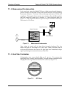
7.2. OXYGEN SENSOR (OPT 65)
7.2.1. Paramagnetic Measurement of O
2
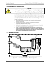
The oxygen sensor used in the T360 analyzer utilizes the fact that oxygen is
attracted into strong magnetic field; most other gases are not, to obtain fast,
accurate oxygen measurements.
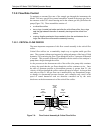
The sensor’s core is made up of two nitrogen filled glass spheres, which are
mounted on a rotating suspension within a magnetic field (Figure 7-7). A mirror
is m
ounted centrally on the suspension and light is shone onto the mirror that
reflects the light onto a pair of photocells. The signal generated by the photocells
is passed to a feedback loop, which outputs a current to a wire winding (in effect,
a small DC electric motor) mounted on the suspended mirror.
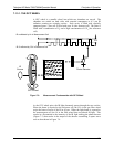
Oxygen from the sample stream is attracted into the magnetic field displacing the
nitrogen filled spheres and causing the suspended mirror to rotate. This changes
the amount of light reflected onto the photocells and therefore the output levels of
the photocells. The feedback loop increases the amount of current fed into the
winding in order to move the mirror back into its original position. The more O
2
present, the more the mirror moves and the more current is fed into the winding
by the feedback control loop.
A sensor measures the amount of current generated by the feedback control loop
which is directly proportional to the concentration of oxygen within the sample
gas mixture.
07272B DCN6552