


Principles of Operation Teledyne API Model T360/T360M Operation Manual
208
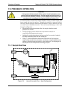
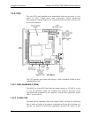
7.4.3.3. GFC WHEEL
A synchronous AC motor turns the GFC wheel motor. For analyzers operating
on 60Hz line power this motor turns at 1800 rpm. For those operating on 50Hz
line power the spin rate is 1500 rpm. The actual spin rate is unimportant within a
large rate since a phase lock loop circuit is used to generate timing pulses for
signal processing.
In order to accurately interpret the fluctuations of the IR beam after it has passed
through the sample gas, the GFC wheel several other timing signals are produced
by other photo emitters/detectors. These devices consist of a combination LED
and detector mounted so that the light emitted by the LED shines through the
same mask on the GFC wheel that chops the IR beam.
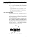
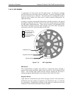
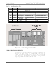
IR Detection Ring
Segment Sensor Ring
M/R Sensor Ring
KEY:
Detection Beam shining
through MEASUREMENT
side of GFC Wheel
Detection Beam shining
through REFERENCE side
of GFC Wheel
Figure 7-13: GFC Light Mask
M/R Sensor
This emitter/detector assembly that produces a signal that shines through a
portion of the mask that allows light to pass for half of a full revolution of the
wheel. The resulting light signal tells the analyzer whether the IR beam is
shining through the measurement or the reference side of the GFC wheel.
Segment Sensor
Light from this emitter/detector pair shines through a portion of the mask that is
divided into the same number of segments as the IR detector ring. It is used by
the synchronous / demodulation circuitry of the analyzer to latch onto the most
stable part of each measurement and reference IR pulse.
07272B DCN6552