


Teledyne API Model T360/T360M Operation Manual Troubleshooting and Service
249
8.5.5. LCD Display Module
Verify the functioning of the front panel display by observing it when power is
applied to the instrument. Assuming that there are no wiring problems and that
the DC power supplies are operating properly, the display screen should light and
show the splash screen with logo and other indications of its state as the CPU
goes through its initialization process.
8.5.6. Relay Board
The relay board PCA (04135) can be most easily checked by observing the
condition of the its status LEDs on the relay board, as described in Section
8.1.4.3, and the associated output when toggled on and off through signal I/O
function in
the diagnostic menu, see Section 8.1.3.
1. If the front panel display responds to button presses and D1 on the relay
board is not flashing, then either the I
2
C connection between the
motherboard and the relay board is bad, or the relay board itself is bad.
2. If D1 on the relay board is flashing and the status indicator for the output in
question (heater power, valve drive, etc.) toggles properly using the signal
I/O function, then the associated control device on the relay board is bad.
Several of the control devices are in sockets and can be easily replaced.
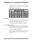
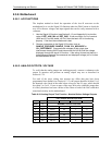
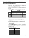
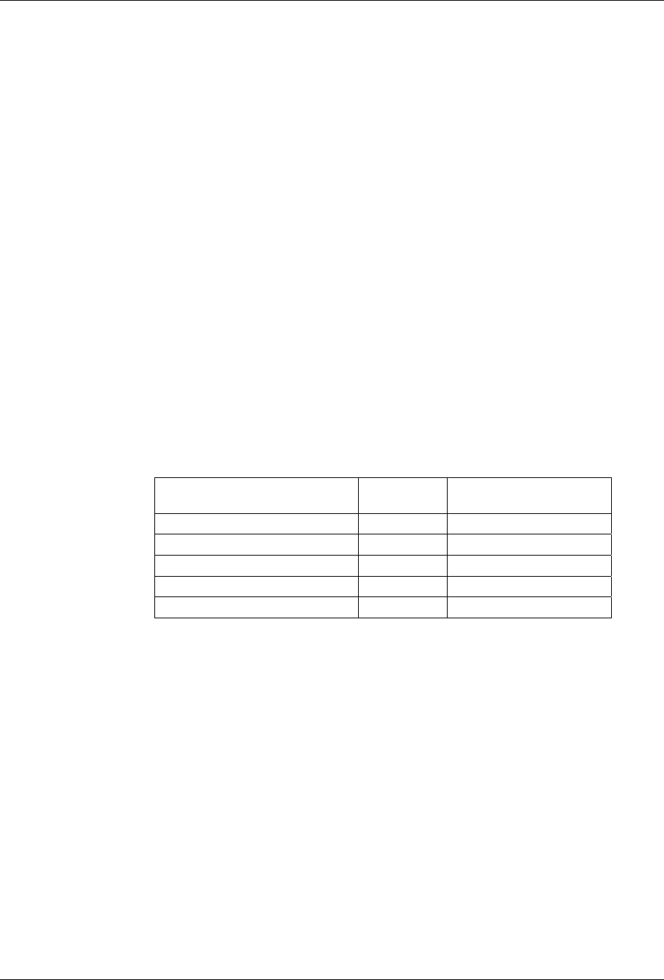
The table below lists the control device associated with a particular function:
Table 8-8: Relay Board Control Devices
FUNCTION
CONTROL
DEVICE
IN SOCKET
Wheel Heater K1 Yes
Bench Heater K2 Yes
Spare AC Control K3 Yes
IZS Valves U4 Yes
IR Source Drive U5 No
The IR source drive output can be verified by measuring the voltage at J16 with
the IR source disconnected. It should be 11.5± 0.5 VDC.
8.5.7. Sensor Assembly
8.5.7.1. SYNC/DEMODULATOR ASSEMBLY
To verify that the Sync/Demodulator Assembly is working follow the procedure
below:
1. Verify that D1 and D2 are flashing (they flash at different rates, see Table
8-3).
If not check the opto pickup assembly, Section 8.5.7.2 and the GFC
whee
l drive, Section 8.5.7.3.
If the wheel d
rive and opto pickup are working properly then verify that
there is 2.4 ±0.1 VAC and 2.5 ±0.15 VDC between digital ground and TP
5 on the sync demod board. If not then check the wiring between the
07272B DCN6552