


Teledyne API Model T360/T360M Operation Manual Troubleshooting and Service
257
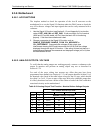
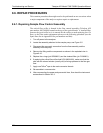
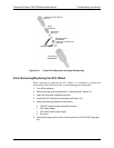
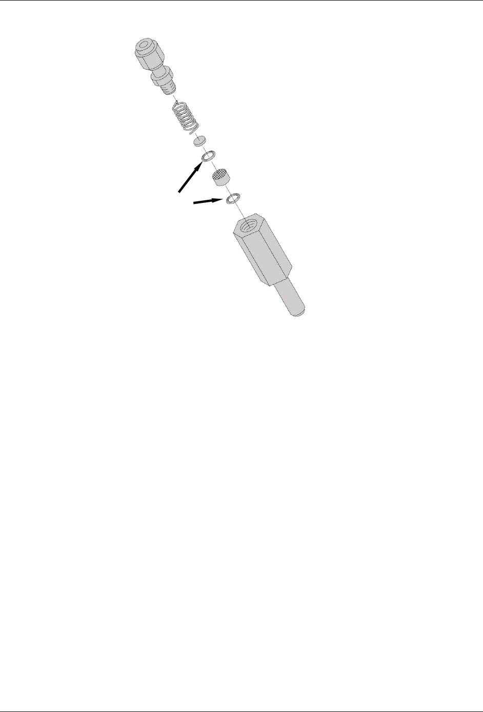
Pneumatic Connector, Male 1/8”
(
P/N FT
_
70
Spring
(
P/N HW
_
20
)
Sintered Filte
r
(
P/N FL
_
01
)
Critical Flow Orifice
(P/N 00094100)
Make sure it is placed with the
jewel down)
O-Ring
(
P/N OR
_
01
)
Purge Housing
(
P/N 000850000
)
Figure 8-10: Critical Flow Restrictor Assembly Disassembly
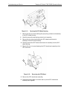
8.6.2. Removing/Replacing the GFC Wheel
When removing or replacing the GFC Wheel it is important to perform the
disassembly in the following order to avoid damaging the components:
1. Turn off the analyzer.
2. Remove the top cover as described in “Getting Started” Section 3.1.
3. Open the in
strument’s hinged front panel.
4. Locate the GFC wheel/motor assembly (see Figure 3-5).
5.
Unpl
ug the following electronic components:
The GFC wheel housing temperature sensor;
GFC wheel heater
GFC wheel motor power supply
IR source
6. Unscrew the purge gas line hex nut and remove the 1/8 inch FEP purge gas
line.
07272B DCN6552