


Principles of Operation Teledyne API Model T360/T360M Operation Manual
194
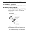
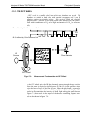
7.1.2. Measurement Fundamentals
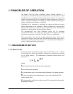
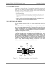
In the most basic terms, the Model T360 uses a high energy heated element to
generate a beam of broad-band IR light with a known intensity (measured during
Instrument calibration. This beam is directed through multi-pass cell filled with
sample gas. The sample cell uses mirrors at each end to reflect the IR beam back
and forth through the sample gas to generate a 2.5 meter absorption path (see
Figure 7-1). This length was chosen to give the anal
y
zer maximum sensitivity to
fluctuations in CO
2
density.
IR
Source
IR Beam
Sample Chamber
Band-Pass Filter
Photo-Detector
Figure 7-1: Measurement Fundamentals
Upon exiting the sample cell, the beam shines through a band-pass filter that
allows only light at a wavelength of 4.3 µm to pass. Finally, the beam strikes a
solid-state photo-detector that converts the light signal into a modulated voltage
signal representing the attenuated intensity of the beam.
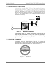
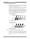
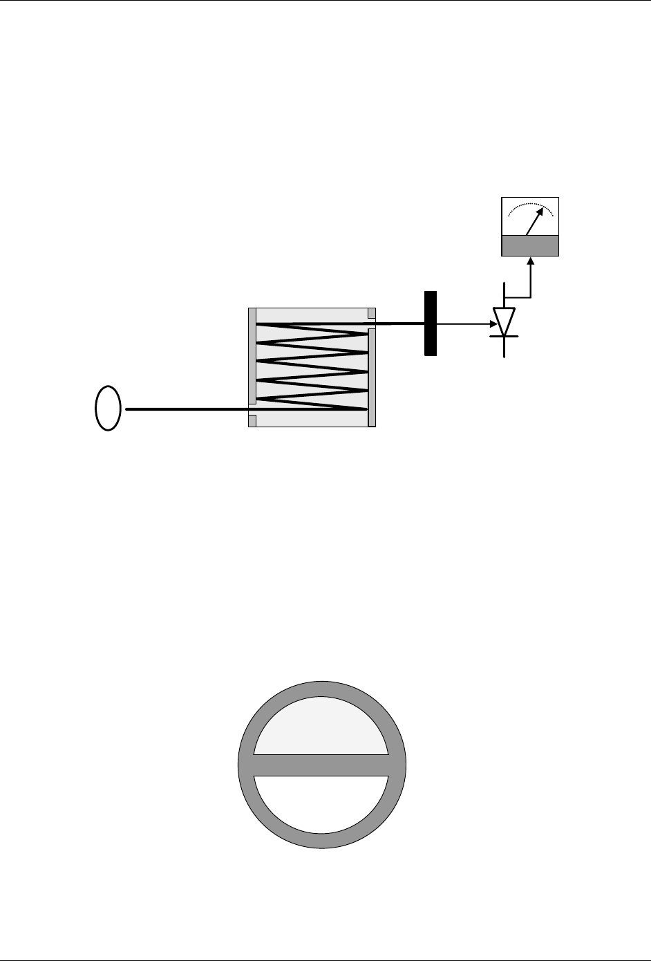
7.1.3. Gas Filter Correlation
Unfortunately, water vapor absorbs light at 4.3 µm too. To overcome the
interfering effects of water vapor the Model T360 adds another component to the
IR light path called a gas filter correlation (GFC) wheel (see Figure 7-2).
Measurement Cell
(Pure N
2
)
Reference Cell
(N
2
with CO
2
)
Figure 7-2: GFC Wheel
07272B DCN6552