


Teledyne API Model T360/T360M Operation Manual Principles of Operation
217
accessible through the SETUP MORE DIAG TEST CHAN OUTPUT
submenu (see Section 4.13.9) of the unit’s software.
Output Loop-back
All four analog outputs are connected back to the A/D converter through a Loop-
back circuit. This permits the voltage outputs to be calibrated by the CPU
without need for any additional tools or fixtures.
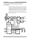
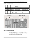
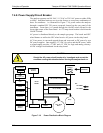
7.4.6.5. INTERNAL DIGITAL I/O
This channel is used to communicate digital status and control signals about the
operation of key components of the Optical Bench. The CPU sends signals to the
synch/demod board that initiate the ELECTRICAL TEST and DARK
CALIBRATION procedures. Likewise, the synch/demod board uses this
interface to send the SYNC warning signal to the CPU (see Sections 4.13.5,
4.13.6, and 8.1.1).
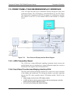
7.4.6.6. EXTERNAL DIGITAL I/O
This External Digital I/O performs two functions: status outputs and control
inputs.
Status Outputs
Logic-Level voltages are output through an optically isolated 8-pin connector
located on the rear panel of the analyzer. These outputs convey good/bad and
on/off information about certain analyzer conditions. They can be used to
interface with certain types of programmable devices (Section 4.15.1.1).
Control Inputs
By applying +5VDC power supplied from an external source such as a PLC or
Data logger (Section 4.15.1.2), Zero and Span calibrations can be initiated by
contact closures on the rear panel.
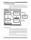
7.4.7. I
2
C Data Bus
An I
2
C data bus is used to communicate data and commands between the CPU
and the touchscreen/display interface and the relay board. I
2
C is a two-wire,
clocked, digital serial I/O bus that is used widely in commercial and consumer
electronic systems. A transceiver on the motherboard converts data and control
signals from the PC-104 bus to I
2
C. The data is then fed to the
touchscreen/display interface and finally onto the relay board.
Interface circuits on the touchscreen/display interface and relay boards convert
the I
2
C data to parallel inputs and outputs. An additional, interrupt line from the
touchscreen to the motherboard allows the CPU to recognize and service button
presses on the touchscreen.
Power up Circuit
This circuit monitors the +5V power supply during start-up and sets the Analog
outputs, external digital I/O ports, and I
2
C circuitry to specific values until the
CPU boots and the instrument software can establish control.
07272B DCN6552