


Principles of Operation Teledyne API Model T360/T360M Operation Manual
216
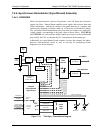
7.4.6.3. THERMISTOR INTERFACE
This circuit provides excitation, termination and signal selection for several
negative-coefficient, thermistor temperature sensors located inside the analyzer.
They are:
Sample Temperature Sensor
The source of this signal is a thermistor located inside the sample chamber of the
Optical Bench. It measures the temperature of the sample gas in the chamber.
This data is used to during the calculation of the CO
2
concentration value.
Bench Temperature Sensor
This thermistor, attached to the sample chamber housing, reports the current
temperature of the chamber housing to the CPU as part of the bench heater
control loop.
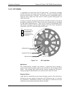
Wheel Temperature Sensor
This thermistor (attached to the heat-sync on the GFC wheel motor assembly)
reports the current temperature of the wheel/motor assembly to the CPU as part of
the Wheel Heater control loop.
Box Temperature Sensor
A thermistor is attached to the motherboard. It measures the analyzer’s inside
temperature. This information is stored by the CPU and can be viewed by the
user for troubleshooting purposes via the front panel display (see Section 8.1.2).
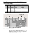
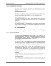
7.4.6.4. ANALOG OUTPUTS
The analyzer comes equipped with four analog outputs: A1, A2, A3 and A4. . In
its standard configuration, the analyzer comes with all four of these channels set
up to output a DC voltage. However, 4-20mA current loop drivers can be
purchased for the first three of these outputs: A2, A2 & A3.
A2 and A1 Output
The first two, A2 and A1 are normally set up to operate in parallel so that the
same data can be sent to two different recording devices. While the names imply
that one should be used for sending data to a chart recorder and the other for
interfacing with a data logger, either can be used for both applications.
Both of these channels output a signal that is proportional to the CO
2
concentration of the sample gas. The A1 and A2 outputs can be slaved together
or set up to operated independently. A variety of scaling factors are available; see
Section 4.13.4 for information on setting the range type and scaling factors for
these output ch
annels.
A3 Output
Analog output channel A3 is only active when the O
2
sensor option is installed in
the T360. In this case, the currently measured O
2
concentration is output.
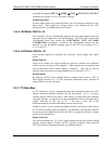
Test Function Output
The fourth analog output, labeled A4 is special. It can be set by the user (see
Section 4.8) to carry the current signal level of any one of the parameters
07272B DCN6552