


Teledyne API - T360/T360M, 360E/360EM Appendix A Menu Trees (05233C DCN6552)
A-28
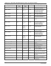
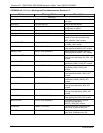
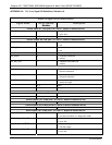
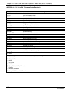
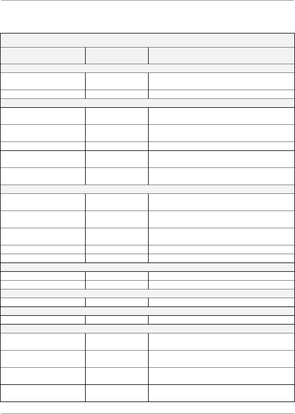
APPENDIX A-4: 300 Series Signal I/O Definitions, Revision L.8
M300E I/O Signal List for Latest Revision
Signal Name Bit or Channel
Number
Description
Internal inputs, U7, J108, pins 9–16 = bits 0–7, default I/O address 322 hex
SYNC_OK 0 1 = sync. OK
0 = sync. error
1–7 Spare
Internal outputs, U8, J108, pins 1–8 = bits 0–7, default I/O address 322 hex
ELEC_TEST 0 1 = electrical test on
0 = off
DARK_CAL 1 1 = dark calibration on
0 = off
2–5 Spare
I2C_RESET 6 1 = reset I2C peripherals
0 = normal
I2C_DRV_RST 7 0 = hardware reset 8584 chip
1 = normal
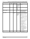
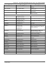
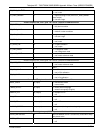
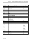
Control inputs, U11, J1004, pins 1–6 = bits 0–5, default I/O address 321 hex
EXT_ZERO_CAL 0 0 = go into zero calibration
1 = exit zero calibration
EXT_SPAN_CAL 1 0 = go into span calibration
1 = exit span calibration
REMOTE_RANGE_HI 2 0 = select high range during contact closure calibration
1 = select low range
3–5 Spare
6–7 Always 1
Control inputs, U14, J1006, pins 1–6 = bits 0–5, default I/O address 325 hex
0–5 Spare
6–7 Always 1
Control outputs, U17, J1008, pins 1–8 = bits 0–7, default I/O address 321 hex
0–7 Spare
Control outputs, U21, J1008, pins 9–12 = bits 0–3, default I/O address 325 hex
0–3 Spare
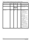
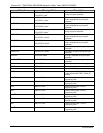
Alarm outputs, U21, J1009, pins 1–12 = bits 4–7, default I/O address 325 hex
ST_SYSTEM_OK2 4 1 = system OK
0 = any alarm condition or in diagnostics mode
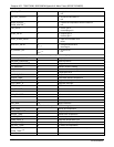
ST_CONC_ALARM_1
8
5 1 = conc. limit 1 exceeded
0 = conc. OK
ST_HIGH_RANGE
10 + 13
5 1 = high auto-range in use
0 = low auto-range
ST_CONC_ALARM_2
8
6 1 = conc. limit 2 exceeded
0 = conc. OK
07272B DCN6552