


Teledyne API Model T360/T360M Operation Manual Troubleshooting and Service
253
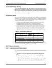
8.5.8.3. ANALOG OUTPUTS: CURRENT LOOP
To verify that the analog outputs with the optional current mode output are
working properly, connect a 250 ohm resistor across the outputs and use a
voltmeter to measure the output as described in Section 4.13.4.4 and then perform
an analog output step test as described in Section 4.13.3.
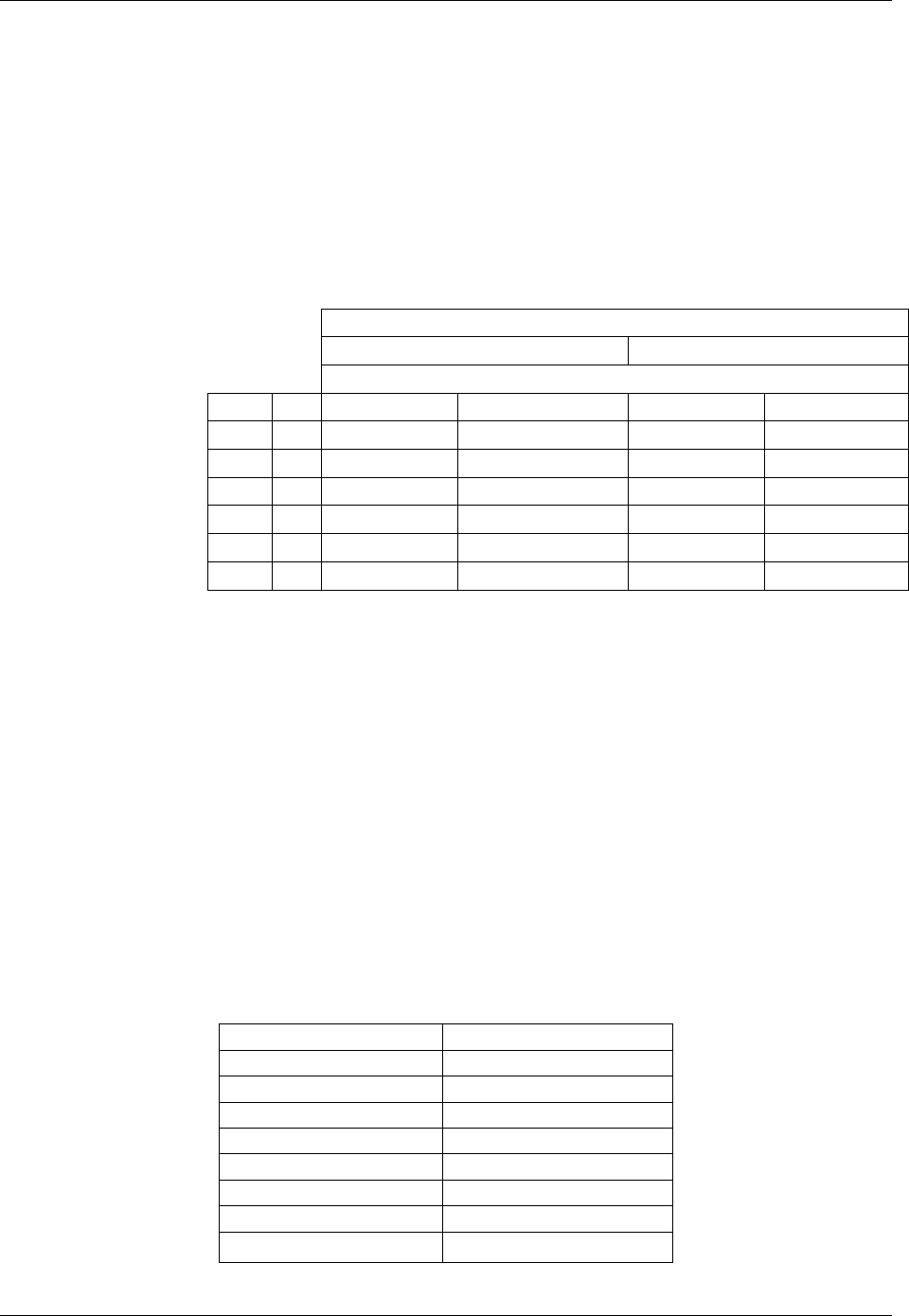
For each step the output s
hould be within 1% of the nominal value listed in the
table below.
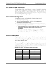
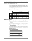
Table 8-11: Analog Output Test Function - Nominal Values Current Outputs
OUTPUT RANGE
2 -20 4 -20
NOMINAL OUTPUT VALUES
STEP % CURRENT V(250 OHMS) CURRENT V(250 OHMS)
1 0 2 mA 0.5V 4 1
2 20 5.6 1.4 7.2 1.8
3 40 9.2 2.3 10.4 2.6
4 60 12.8 3.2 13.6 3.4
5 80 16.4 4.1 16.8 4.2
6 100 20 5 20 5
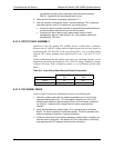
8.5.8.4. STATUS OUTPUTS
The procedure below can be used to test the Status outputs (Figure 4-13):
1. Connect a jumper between the “D“ pin and the “” pin on the status output
connector.
2. Connect a 1000 ohm resistor between the “+” pin and the pin for the status
output that is being tested.
3. Connect a voltmeter between the “” pin and the pin of the output being
tested (see table below).
Under the DIAG SIGNAL I/O menu (see Section 8.1.3), scroll through the
inputs and outputs until you get to the output in question. Alternately turn on and
off the output noting the voltage on the voltmeter, it should vary between 0 volts
for ON and 5 volts for OFF.
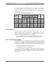
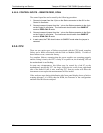
Table 8-12: Status Outputs Check
PIN (LEFT TO RIGHT) STATUS
1 SYSTEM OK
2 CONC VALID
3 HIGH RANGE
4 ZERO CAL
5 SPAN CAL
6 DIAG MODE
7 ALRM1
8 ALRM2
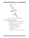
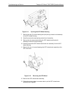
07272B DCN6552