


Troubleshooting and Service Teledyne API Model T360/T360M Operation Manual
252
8.5.8. Motherboard
8.5.8.1. A/D FUNCTIONS
The simplest method to check the operation of the A-to-D converter on the
motherboard is to use the Signal I/O function under the DIAG menu to check the
two A/D reference voltages and input signals that can be easily measured with a
voltmeter.
1. Use the Signal I/O function (see Section 8.1.3 and Appendix A) to view the
value of
REF_4096_MV and REF_GND. If both are within 3 mV of nominal
(4096 and 0), and are stable, ±0.5 mV then the basic A/D is functioning
properly. If not then the motherboard is bad.
2. Choose a parameter in the Signal I/O function such as
SAMPLE_PRESSURE, SAMPLE_FLOW, CO
2
_MEASURE or
CO
2
_REFERENCE. Compare these voltages at their origin (see
interconnect drawing 04215 and interconnect list 04216) with the voltage
displayed through the signal I/O function. If the wiring is intact but there is a
large difference between the measured and displayed voltage (±10 mV) then
the motherboard is bad.
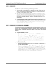
8.5.8.2. ANALOG OUTPUTS: VOLTAGE
To verify that the analog outputs are working properly, connect a voltmeter to the
output in question and perform an analog output step test as described in
Section 4.13.4.
For each of the steps, ta
king into account any offset that may have been
programmed into channel (see Section 4.13.3), the output should be within 1% of
the nom
inal value listed in the table below except for the 0%
step, which should
be within 2 to 3 mV. If one or more of the steps fails to be within this range then
it is likely that there has been a failure of the either or both of the DACs and their
associated circuitry on the motherboard.
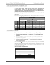
Table 8-10: Analog Output Test Function - Nominal Values Voltage Outputs
FULL SCALE OUTPUT VOLTAGE
100MV 1V 5V 10V
STEP % NOMINAL OUTPUT VOLTAGE
1 0 0 0 0 0
2 20 20 mV 0.2 1 2
3 40 40 mV 0.4 2 4
4 60 60 mV 0.6 3 6
5 80 80 mV 0.8 4 8
6 100 100 mV 1.0 5 10
07272B DCN6552