


Troubleshooting and Service Teledyne API Model T360/T360M Operation Manual
230
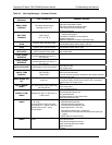
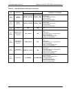
TEST
FUNCTIONS
INDICATED FAILURE(S)
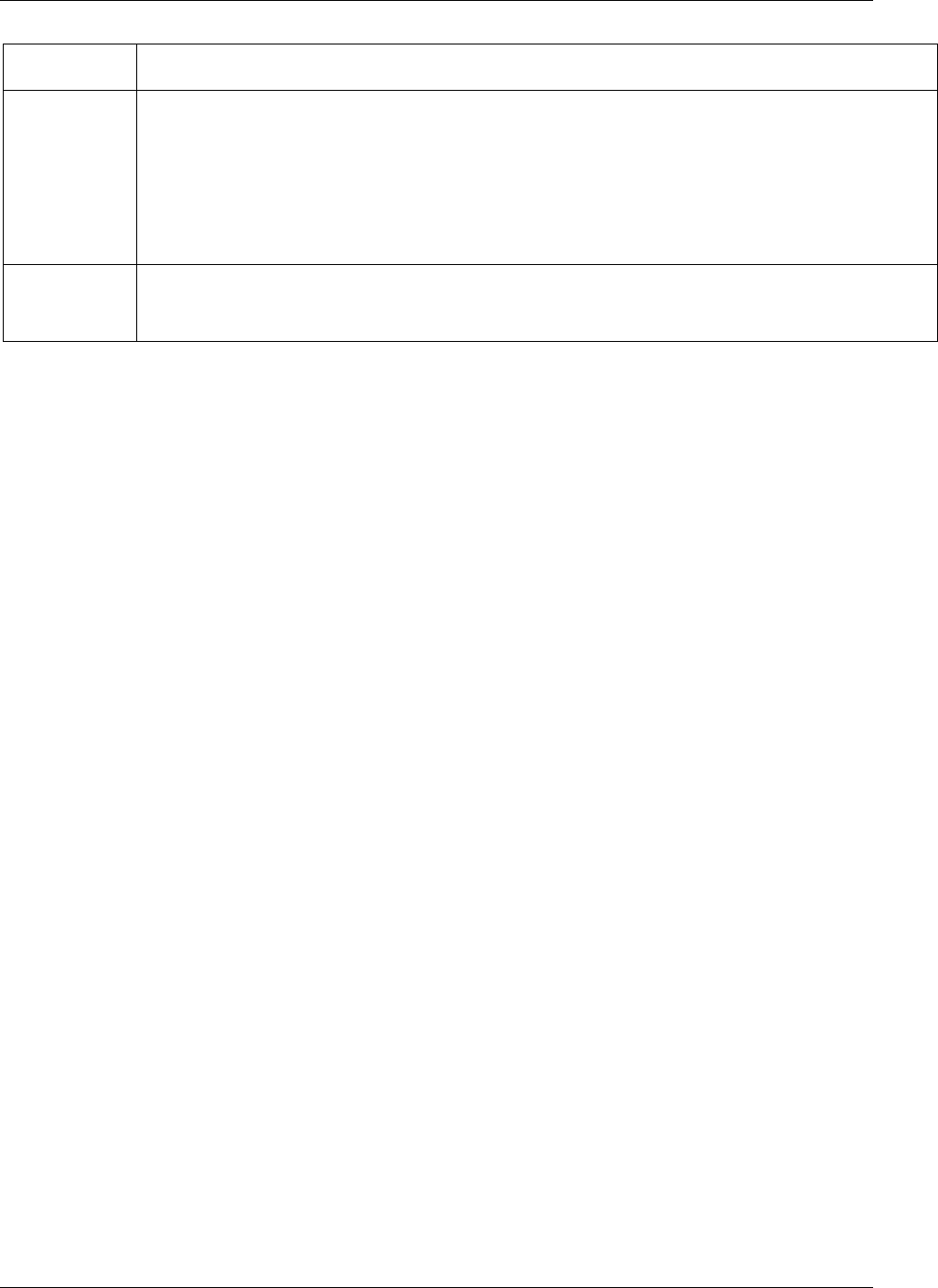
SLOPE
Values outside range indicate:
Contamination of the zero air or span gas supply
Instrument is miss-calibrated
Blocked gas flow
Contaminated or leaking GFC wheel (either chamber)
Faulty IR photo-detector
Faulty sample faulty IR photo-detector pressure sensor (P1) or circuitry
Invalid M/R ratio (see above)
Bad/incorrect span gas concentration due.
OFFSET
Values outside range indicate:
Contamination of the zero air supply
Contaminated or leaking GFC wheel (either chamber)
Faulty IR photo-detector
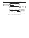
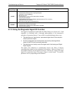
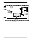
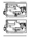
8.1.3. Using the Diagnostic Signal I/O Function
The Signal I/O parameters found under the DIAG Menu (see Section 4.13.2 and
Appendix A) combined with a thorough understanding of the instrument’s
principles of operation (Section 7) are useful for troubleshooting in three ways:
The technician can view the raw, unprocessed signal level of the analyzer’s
critical inputs and outputs.
All of the components and functions that are normally under algorithmic
control of the CPU can be manually exercised.
The technician can directly control the signal level of the Analog and Digital
Output signals.
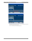
This allows the technician to systematically observe the effect of directly
controlling these signals on the operation of the analyzer. Below in Figure 8-2 is
an example of how to use the signal I/O
menu to view the raw voltage of an input
signal or to control the state of an output voltage or control signal. The specific
parameter will vary depending on the situation.
07272B DCN6552