


Teledyne API Model T360/T360M Operation Manual Getting Started
57
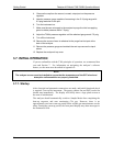
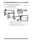
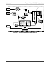
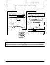
3.7.4. Functional Checks
1. After the analyzer’s components has warmed up for at least 30 minutes,
verify that the software properly supports any hardware options that were
installed.
2. Check to make sure that the analyzer is functioning within allowable
operating parameters. Appendix C includes a list of test functions viewable
from the analyzer’s front panel as well as their expected values. These
functions are also useful tools for diagnosing performance problems with
your analyzer (Section11.1.2). The enclosed Final Test and Validation Data
sheet (part number 04307) lists these values before the instrument left the
factory.
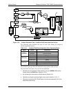
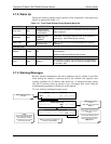
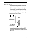
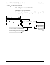
To view the current values of these parameters press the following button
sequence on the analyzer’s front panel. Remember until the unit has completed
its warm up these parameters may not have stabilized.
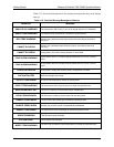
RANGE
RANGE1
1
RANGE2
1
O
2
RANGE
2
STABIL
MEAS
REF
MR RATIO
PRES
SAMP FL
SAMP TEMP
BENCH TEMP
WHEEL TEMP
BOX TEMP
PHT DRIVE
SLOPE
OFFSET
TEST
TIME
SAMPLE RANGE = 500.000 PPM CO2 = XXX.X
< TST TST > CAL SETUP
1
Only appears instrument is set
for DUAL or AUTO reporting
range modes.
2
Only appears if O
2
Sensor
Option is installed.
Toggle <TST TST> buttons
to scroll throu
g
h list of
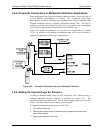
3. If your network is running a dynamic host configuration protocol (DHCP)
software package, the Ethernet feature will automatically configure its
interface with your LAN. (See Section 4.11.6.1). This configuration is useful
for quickly ge
tting an instru
ment up and running on a network. However, for
permanent Ethernet connections, a static IP address should be used. (See
Section 4.11.6.2).
07272B DCN6552