


Principles of Operation Teledyne API Model T360/T360M Operation Manual
212
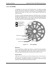
7.4.4.3. SYNC/DEMOD STATUS LED’S
The following two status LED’s located on the synch/demod board provide
additional diagnostic tools for checking the GFC wheel rotation.
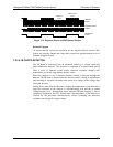
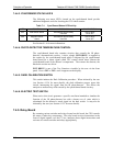
Table 7-1: Sync/Demod Status LED Activity
LED FUNCTION STATUS OK FAULT STATUS
D1
M/R Sensor Status
LED flashes approximately
2/second
LED is stuck
ON or OFF
D2 Segment Sensor
Status
LED flashes approximately
6/second
LED is stuck
ON or OFF
See Section 8.1.4 for more information.
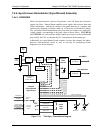
7.4.4.4. PHOTO-DETECTOR TEMPERATURE CONTROL
The synch/demod board also contains circuitry that controls the IR photo-
detector’s thermoelectric coolers. A drive voltage, PHT DRIVE, is supplied to
the coolers by the synch/demod board which is adjusted by the synch/demod
board based on a return signal called TEC control which alerts informs the
synch/demod board of the detector’s temperature. The warmer the detector, the
harder the coolers are driven.
PHT DRIVE is one of the Test Functions viewable by the user via the front
panel. Press <TST or TST> until it appears on the display.
7.4.4.5. DARK CALIBRATION SWITCH
This switch initiates the Dark Calibration procedure. When initiated by the user
(see Section 4.13.6 for more details), the dark calibration process opens this
switch, interrupting
the signal from the IR photo-detector. This allows the
analyzer to measure any offset caused by the synch/demod board circuitry.
7.4.4.6. ELECTRIC TEST SWITCH
When active this circuit generates a specific waveform intended to simulate the
function of the IR photo-detector but with a known set of value which is
substituted for the detector’s actual signal via the dark switch. It may also be
initiated by the user (see Section 4.13.5 for more details).
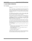
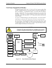
7.4.5. Relay Board
By actuating various switches and relays located on this board, the CPU controls
the status of other key components. The relay board receives instructions in the
form of digital signals over the I
2
C bus, interprets these digital instructions and
activates its various switches and relays appropriately.
07272B DCN6552