


Principles of Operation Teledyne API Model T360/T360M Operation Manual
202
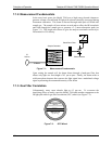
The actual flow rate of gas through the orifice (volume of gas per unit of time),
depends on the size and shape of the aperture in the orifice. The larger the hole,
the more gas molecules, moving at the speed of sound, pass through the orifice.
Because the flow rate of gas through the orifice is only related to the minimum
2:1 pressure differential and not absolute pressure the flow rate of the gas is also
unaffected by degradations in pump efficiency due to age.
The critical flow orifice used in the Model T360 is designed to provide a flow
rate of 800 cm
3
/min.
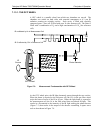
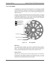
7.3.3. Purge Gas Pressure Control
In order to ensure that all of the ambient CO
2
is purged from the GFC Wheel
housing an adequate supply of dried air, scrubbed of CO
2
must be supplied to the
PURGE AIR inlet at the back of the instrument.
The minimum gas pressure of the source of purge air should be 7.5 psig.
If the source of the purge air is shared by a Teledyne API’s T700 the
minimum gas pressure should be 25 psig and should not exceed 35 psig.
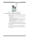
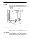
In order to maintain the proper pressure differential between the inside of the
GFC wheel housing and ambient air, the T360 design includes a manually
adjustable pressure regulator (see Figure 3-5 and Figure 3-6 for
Purge Gas Pressure
Regulator
) that maintains the pressure of the purge air feed at 7.5 psig.
7.3.4. Particulate Filter
The Model T360 Analyzer comes equipped with a 47 mm diameter, Teflon,
particulate filter with a 5 micron pore size. The filter is accessible through the
front panel, which folds down to allow access, and should be changed according
to the suggested maintenance schedule described in Table 6-1.
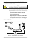
7.3.5. Pneumatic Sensors
7.3.5.1. SAMPLE PRESSURE SENSOR
An absolute value pressure transducer plumbed to the outlet of the sample
chamber is used to measure sample pressure. The output of the sensor is used to
compensate the concentration measurement for changes in air pressure. This
sensor is mounted to a printed circuit board with the sample flow sensor on the
sample chamber; see the following section and Figure 3-5.
7.3.5.2. SAMPLE FLOW SENSOR
A thermal-mass flow sensor is used to measure the sample flow through the
analyzer. The sensor is calibrated at the factory with ambient air or N2, but can
be calibrated to operate with samples consisting of other gases such as CO
2
. This
sensor is mounted to a printed circuit board with the Sample Pressure sensor on
the sample chamber; see the previous section and Figure 3-5.
07272B DCN6552