


Teledyne API Model T360/T360M Operation Manual Troubleshooting and Service
233
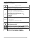
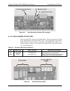
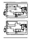
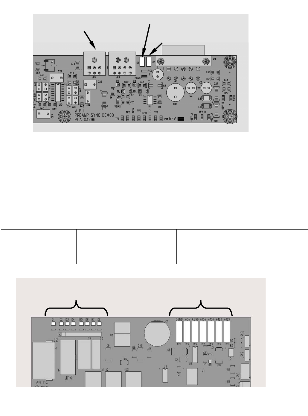
D1 – M/R Sensor Status
D2 – Segment Sensor Status
JP4 Connector to Opto-Pickup
Board
Figure 8-4: Sync/Demod Board Status LED Locations
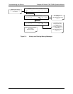
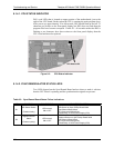
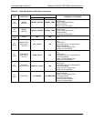
8.1.4.3. RELAY BOARD STATUS LEDS
There are eight LEDs located on the Relay Board. The most important of which
is D1, which indicates the health of the I
2
C bus. If D1 is blinking, the other faults
LEDs (Table 8-5) can be used in conjunction with DIAG
menu signal I/O to
identify hardware failures of the relays and switches on the relay (See Section
4.13.2 and Appendix D).
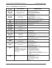
Table 8-4: I2C Status LED Failure Indications
LED FUNCTION FAULT STATUS INDICATED FAILURE(S)
D1
(Red)
I
2
C bus Health
(Watchdog
Circuit)
Continuously ON
or
Continuously OFF
Failed/Halted CPU
Faulty Motherboard, or Relay Board
Faulty Connectors/Wiring to/from Relay Board
Failed/Faulty +5 VDC Power Supply (PS1)
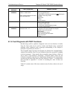
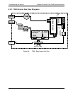
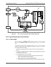
STATUS LED’s
DC VOLTAGE TEST
POINTS
RELAY PCA
Figure 8-5: Relay Board Status LEDs
07272B DCN6552