


Troubleshooting and Service Teledyne API Model T360/T360M Operation Manual
260
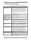
8.7. FREQUENTLY ASKED QUESTIONS
The following is a list from the Teledyne API’s Technical Support Department of
the most commonly asked questions relating to the Model CO
2
Analyzer.
Question Answer
Why does the instrument not
appear on the LAN or Internet?
Most problems related to Internet communications via the Ethernet
card will be due to problems external to the instrument (e.g. bad
network wiring or connections, failed routers, malfunctioning
servers, etc.) However, there are several symptoms that indicate
the problem may be with the Ethernet card itself. If neither of the
Ethernet cable’s two status LED’s (located on the back of the cable
connector) is lit while the instrument is connected to a network:
Verify that the instrument is being connected to an active
network jack.
Check the internal cable connection between the Ethernet card
and the CPU board.
How do I get the instrument to
zero / Why is the zero button not
displayed?
See Section 8.3.4 Inability to zero.
How do I get the instrument to
span / Why is the span button not
displayed?
See Section 8.3.3 Inability to span.
Why does the ENTR button
sometimes disappear on the
Front Panel Display?
During certain types of adjustments or configuration operations, the
ENTR button will disappear if you select a setting that is
nonsensical (such as trying to set the 24-hour clock to 25:00:00) or
out of the allowable range for that parameter (such as selecting a
DAS Holdoff period of more than 20 minutes). Once you adjust the
setting in question to an allowable value, the
ENTR button will re-
appear.
Is there an optional midpoint
calibration?
There is an optional mid point linearity adjustment; however,
midpoint adjustment is applicable only to applications where CO
2
measurements are expected above 100 ppm. Call Teledyne
Instrument’s Technical Support Department for more information on
this topic.
How do I make the display and
data logger analog input agree?
This most commonly occurs when an independent metering device
is used besides the data logger/recorded to determine gas
concentration levels while calibrating the analyzer. These
disagreements result from the analyzer, the metering device and
the data logger having slightly different ground levels. Both the
electronic scale and offset of the analog outputs can be adjusted
(see Section 4.13.4.3). Alternatively, use the data log
ger itself a
s
the metering device during calibrations procedures.
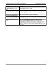
How do I perform a leak check? See Section 6.3.3.
How do I measure the sample
flow
Sample flow is measured by attaching a calibrated rotameter, wet
test meter, or other flow-measuring device to the sample inlet port
when the instrument is operating. The sample flow should be 800
cm
3
/min 10%. See Section 6.3.4.
07272B DCN6552