


Troubleshooting and Service Teledyne API Model T360/T360M Operation Manual
250
sync/demod and opto pickup assembly (see interconnect drawing
04216). If good then the sync/demod board is bad.
2. Verify that the IR source is operating, Section 8.5.7.4.
3. With the anal
yzer connected to zero air, measure between TP11 (measure)
and analog ground, and TP12 (reference) and analog ground.
If they are similar to values recorded on the factory data sheet then there
is likely a problem with the wiring or the A/D converter.
If they are not then either the sync demodulator board or the IR-
photodetector are bad. See Section 8.4.1.4 for problems with the IR-
photod
etecto
r TEC drive.
8.5.7.2. OPTO PICKUP ASSEMBLY
Operation of the opto pickup PCA (04088) can be verified with a voltmeter.
Measure the AC and DC voltage between digital ground on the relay board, or
touchscreen and TP1 and TP2 on the sync pickup PCA. For a working board,
with the GFC motor spinning, they should read 2.4 ±0.1 VAC and 2.5 ±0.15
VDC.
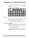
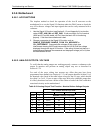
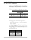
Further confirmation that the pickups and motor are operating properly can be
obtained by measuring the frequency at TP1 and TP2 using a frequency counter,
a digital volt meter with a frequency counter, or an oscilloscope per the table
below.
Table 8-9: Opto Pickup Board Nominal Output Frequencies
NOMINAL MEASURED FREQUENCY
AC MAINS FREQ. TP1 TP2
50 Hz 25 300
60 Hz 30 360
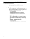
8.5.7.3. GFC WHEEL DRIVE
If the D1 and D2 on the sync demodulator board are not flashing then:
1. Check for power to the motor by measuring between pins 1 and 3 on the
connector feeding the motor. For instruments configured for 120 or 220-
240VAC there should be approximately 88 VAC for instruments configured
for 100VAC, it should be the voltage of the AC mains, approximately
100VAC.
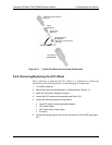
2. Verify that the frequency select jumper, JP4, is properly set on the Relay
Board. For 50 Hz operation it should be installed. For 60 Hz operation may
either be missing or installed in a vertical orientation.
3. If there is power to the motor and the frequency select jumper is properly set
then the motor is likely bad. See Section 8.6.2 for instructions on removing
and re
pla
cing the GFC assembly that the motor is bolted to.
07272B DCN6552