


Troubleshooting and Service Teledyne API Model T360/T360M Operation Manual
232
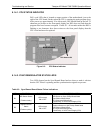
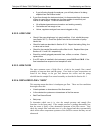
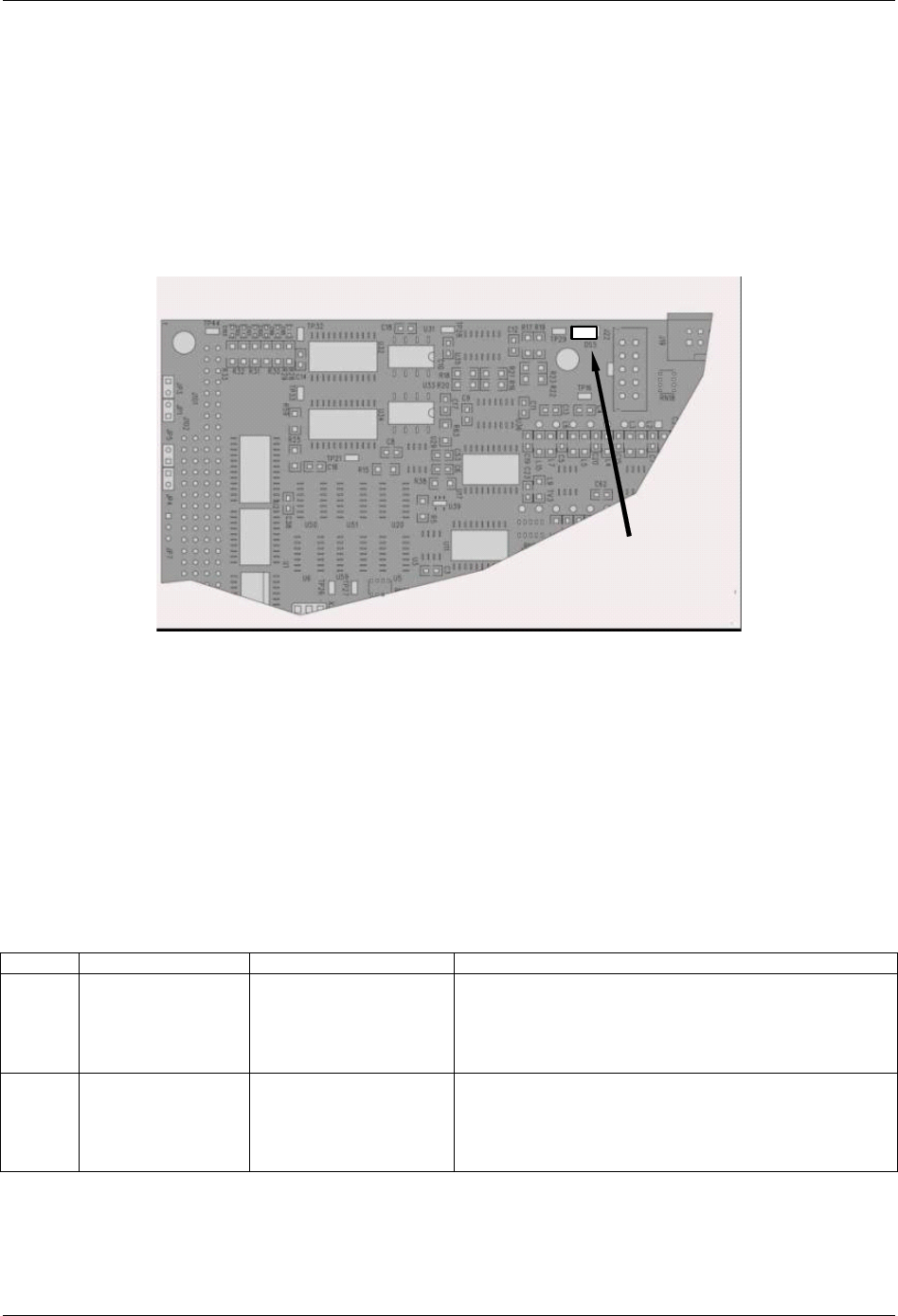
8.1.4.1. CPU STATUS INDICATOR
DS5, a red LED, that is located on upper portion of the motherboard, just to the
right of the CPU board, flashes when the CPU is running the main program loop.
After power-up, approximately 30 to 60 seconds, DS5 should flash on and off. If
characters are written to the front panel display but DS5 does not flash then the
program files have become corrupted. If after 30 – 60 seconds neither the DS5 is
flashing or no characters have been written to the front panel display then the
CPU is bad and must be replaced.
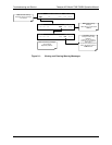
Motherboard
CPU Status LED
Figure 8-3: CPU Status Indicator
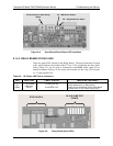
8.1.4.2. SYNC DEMODULATOR STATUS LED’S
Two LEDs located on the Sync/Demod Board and are there to make it obvious
that the GFC Wheel is spinning and the synchronization signals are present:
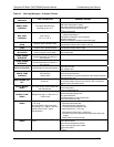
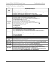
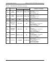
Table 8-3: Sync/Demod Board Status Failure Indications
LED FUNCTION FAULT STATUS INDICATED FAILURE(S)
D1
M/R Sensor Status
(Flashes slowly)
LED is stuck
ON or OFF
GFC Wheel is not turning
M/R Sensor on Opto-Pickup Board failed
Sync/Demod Board failed
JP 4 Connector/Wiring faulty
Failed/Faulty +5 VDC Power Supply (PS1)
D2
Segment Sensor
Status
(Flashes quickly)
LED is stuck
ON or OFF
GFC Wheel is not turning
Segment Sensor on Opto-Pickup Board failed
Sync/Demod Board failed
JP 4 Connector/Wiring faulty
Failed/Faulty +5 VDC Power Supply (PS1)
07272B DCN6552