


Concord Ultra
19
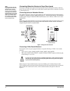
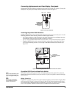
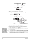
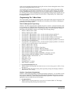
Figure 21. Connecting the SuperBus to the Panel
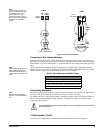
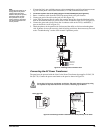
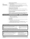
SuperBus 2000 Wireless Gateway Module (60-861)
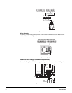
Connect the SuperBus 2000 Wireless Gateway Module to the panel as shown in Figure 22.
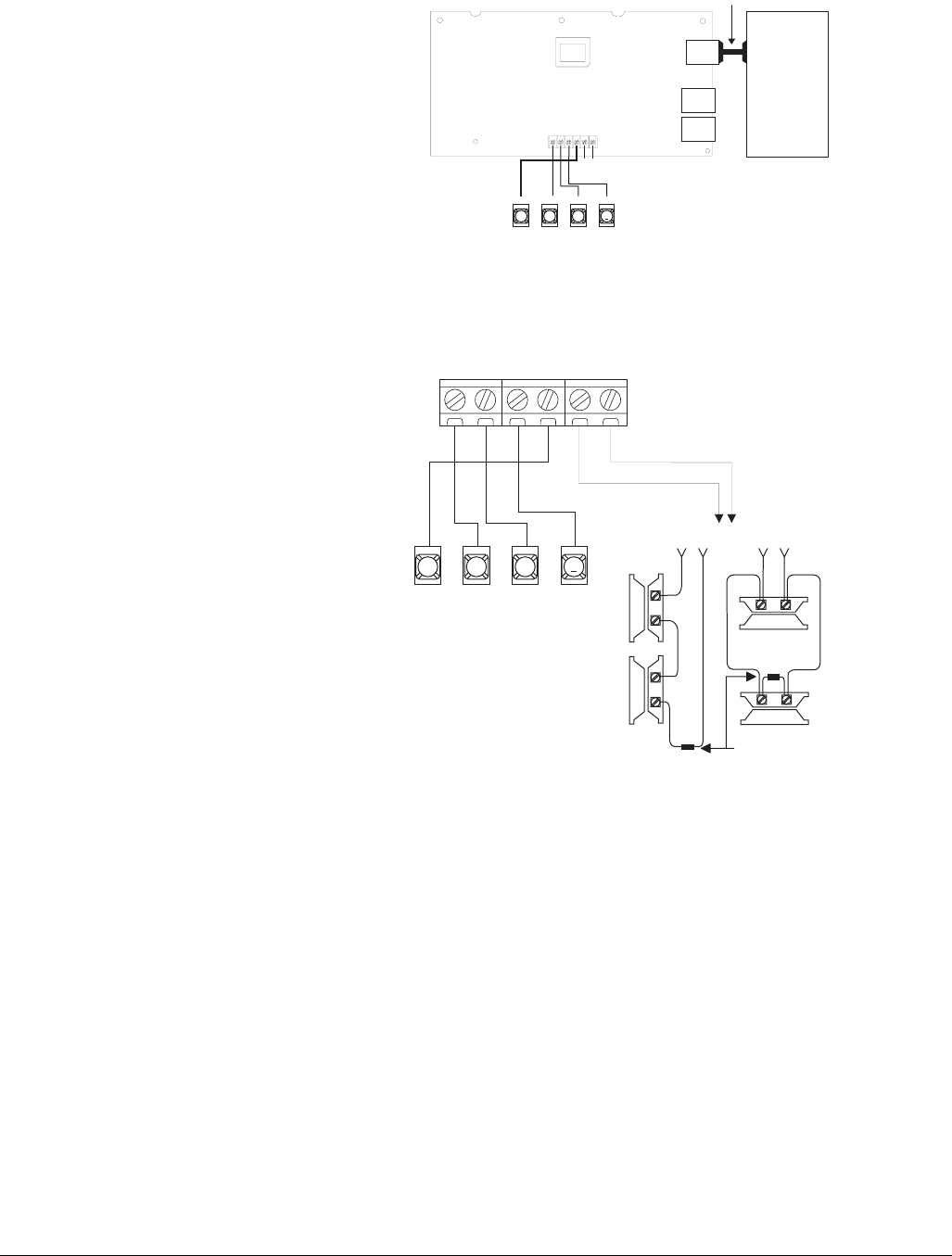
Figure 22. Connecting the Wireless Gateway Module to the Panel
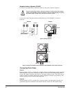
Setting Device Address on SuperBus 2000 Devices
When the panel is powered up it automatically assigns device addresses and unit numbers to
SuperBus 2000 devices, enabling the panel and module to communicate.
Note
The panel cannot be used
on a digital or PBX phone
line. These systems are
designed for digital type
devices only, operating any-
where from 5 volts DC and
up. The panel uses an ana-
log modem and does not
have a digital converter,
adapter, or interface to oper-
ate through such systems.
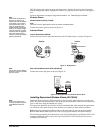
Installing an RJ-31X Phone Jack (13-081)
Use the following guidelines when installing an RJ-31X phone jack for system control by phone
and central station monitoring.
• Locate the RJ-31X jack (CA-38A in Canada) no further than five feet from the panel.
• The panel must be connected to a standard analog (loop-start) phone line, that provides 48
volts DC (on-hook or idle) which increases to 89 to 105 volts DC (ring voltage).
• For full line seizure, install an RJ-31X phone jack on the premises phone line so the panel is
ahead of all phones and other devices on the line. This allows the panel to take control of the
phone line when an alarm occurs, even if the phone is in use or off-hook.
6 0 7 3 4 g 3 0 6 d d s f
1 2 3 4 5 6
Z C O M
Z O N E 1
3 4 5
6
+ 12 V
A
B
G N D
B U S
Panel
Terminals
Automation
Device
Automation Module Circuit Board
DB-9 Serial Cable
6 0 8 6 1 G 0 3 A .D S F
3 4 5
6
+ 1 2 V
A
B
G N D
B U S
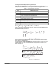
+ 1 2 V
A B G N D
Z 1
Z C O M
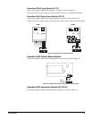
Module Wiring Terminals
Panel Terminals
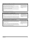
UL-Listed
Normally
Closed (N/C)
Contacts
in Series
UL-Listed
Normally
Open (N/C)
Contacts
in Parallel
OR
2.0K Ohm EOL Resistor 01-022
(Install at Last Contact)