


Concord Ultra 16
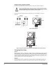
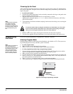
Connecting Alphanumeric and Fixed Display Touchpads
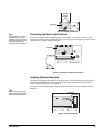
Alphanumeric and Fixed Display touchpads use the same color-coded wire scheme. Connect the
touchpads to the panel power output and bus terminals as shown in Figure 14.
Figure 14. Wiring Touchpads
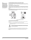
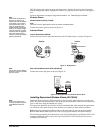
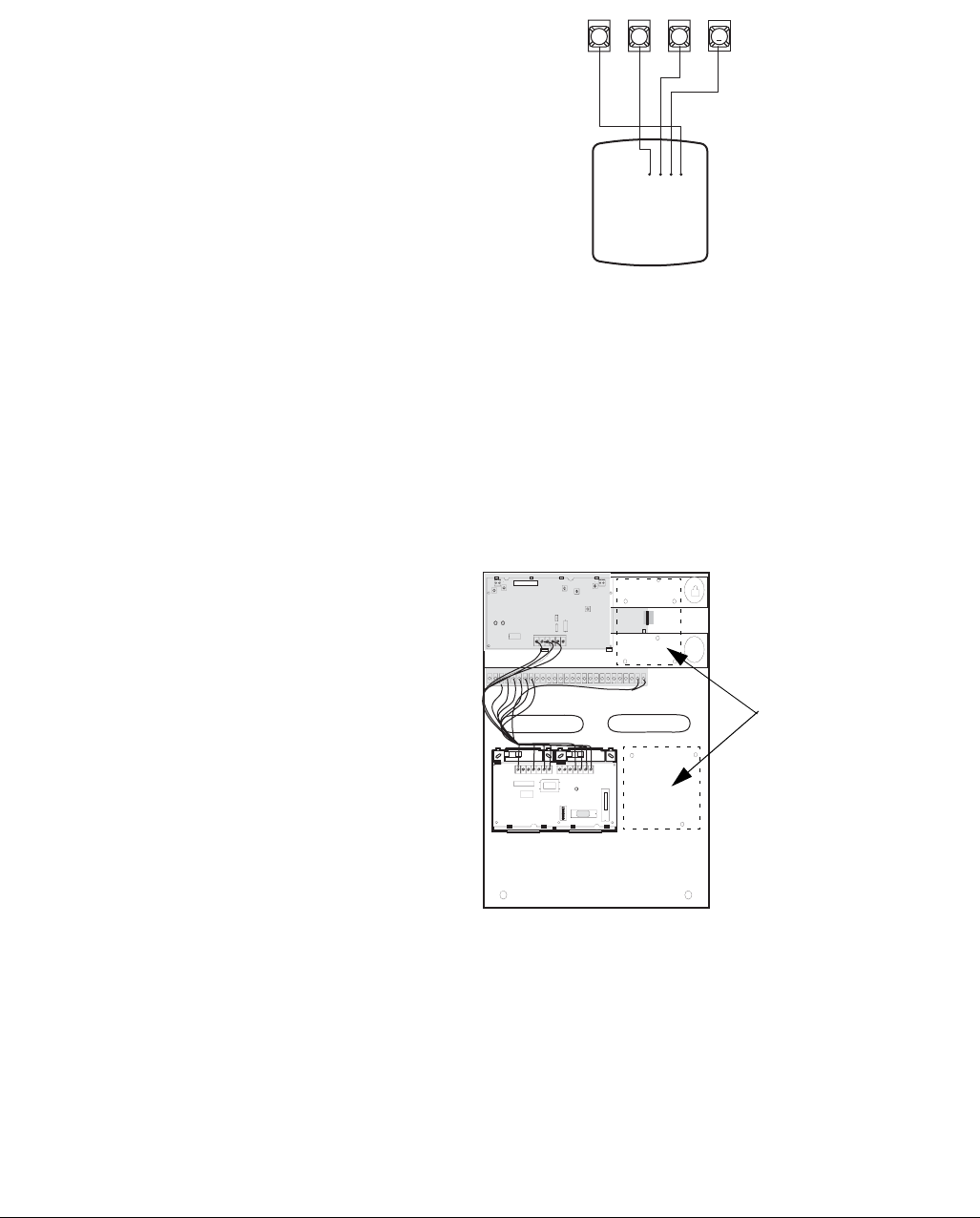
Installing SuperBus 2000 Modules
SuperBus 2000 modules can be installed inside the panel cabinet or away from the panel. Use the
following guidelines when installing modules inside the panel cabinet:
• Up to 16 bus modules can be connected to the panel. (The transceiver and Phone Interface/
Voice Module each count as one module, leaving 14 available.)
• Up to 2 of the SuperBus 2000 modules listed in Table 1 can be mounted inside the cabinet.
• SuperBus 2000 modules can be mounted inside the cabinet either to the right of the Trans-
ceiver on the mounting brackets or to the right of the Phone Interface/Voice Module (see
Figure 15).
Figure 15. Mounting SuperBus 2000 Modules Inside the Cabinet
SuperBus 2000 Phone Interface/Voice Module
Note
In UL Listed installations, the
Phone Interface/Voice Mod-
ule is for supplementary use
only.
The module requires panel power and bus connections (already wired), phone line connection
through panel terminals and DB-8 cord (from an RJ-31X jack), and speaker connection through
panel terminals.
Note
For RJ-31X connections,
see “Installing an RJ-31X
Phone Jack (13-081).
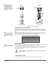
Wiring—Phone Line
For partition 1, connect the phone line to the module through the panel terminals using the DB-8
cord (from an RJ-31X jack) as shown in Figure 16. Much of the connection between the Panel
Circuit Board and the Phone Interface/Voice Module is pre-wired. For partition 2 phone connec-
tion, see the SuperBus 2000 Phone Interface/Voice Module Installation Instructions.
SuperBus 2000
Fixed Display
Touchpad or
LCD Alphanumeric
Touchpads
+12V/Red
Bus A/Green
Bus B/White
GND/Black
GND +12V
ABUSB
4
3
5
6
ID: XXXXXXXX
Locations for
mounting SuperBus
Modules