Concord Ultra 10
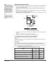
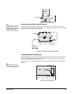
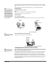
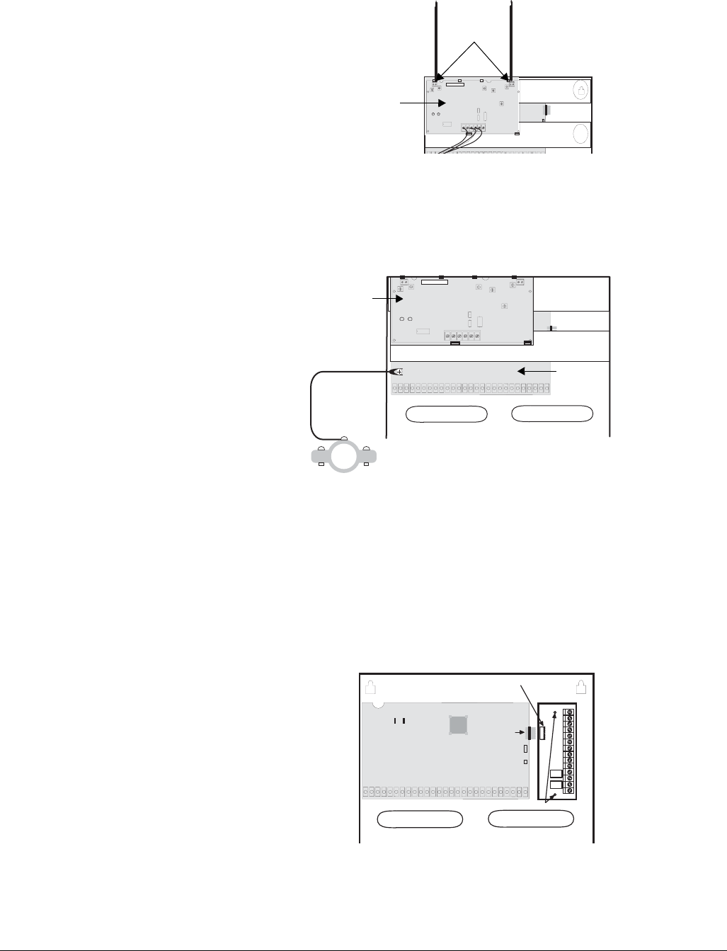
Figure 4. Installing the Antennas
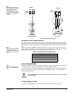
Note
For best results, it is recom-
mended that you crimp a
spade lug on the wire end at
the panel and secure the lug
under the circuit board
screw as shown in Figure 5.
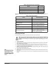
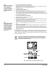
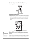
Connecting the Panel to Earth Ground
For maximum protection from lightning strikes and transients, connect the lower-left circuit
board screw to earth ground as shown in Figure 5. Use 16-gauge, solid copper wire from an earth
grounded cold water pipe clamp to the panel.
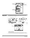
Figure 5. Connecting the Panel to Earth Ground
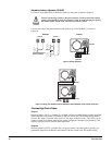
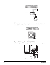
Installing Optional SnapCards
The SnapCard Header on the right side of the panel allows for the installation of one SnapCard.
Install the desired SnapCard onto the panel SnapCard Header and secure it in place with two
screws, included with the card (see Figure 6).
Connect all necessary input/output wiring using the Installation Instructions included with the
SnapCard.
Note
Figure 6 shows the control
panel without the transceiver
and its mounting brackets.
Figure 6. Installing a SnapCard
ID: XXXXXXXX
Connect
To Inside
Terminals
Transceiver
ID: XXXXXXXX
To Water Pipe
Pipe
Ground Clamp
Transceiver
Circuit
Board
Panel
Connector
SnapCard
Screw Locations
SnapCard
Header


